Photo Realistic Rendering
Modelling of American Chopper in Solidworks
INTRODUCTION
Solidworks is a widely used modelling software, typically starting from 2D sketching to 3D parts out of it. In this particular project an American Chopper is used to understand the software working from the very basics and getting familiar with the UI of the software along with the tools used to model the chopper.
Solidworks 2018 version is used to complete this project.
OBJECTIVE
- Model the individual parts of the American Chopper.
- Assemble the parts of the American Chopper
- Appling Decals, appearances, camera, lights etc.
- Finally rendering the American chopper to photorealistic model using photoview 360.
DESIGN METHODOLOGY
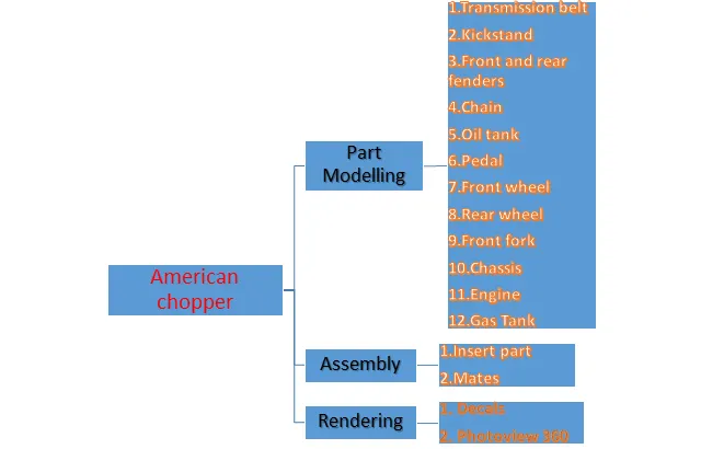
The following layout drawing will depict the approach used to create the model in the software.
PART MODELLING
All the parts modelled are briefly explained as follows along with the features used to create the model.
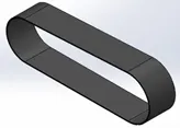
- Transmission Belt
Used to transmit power from engine to gearbox.
Features used to create it:
- Sketch: A 2D representation of the model expressed with entities like line, rectangle, spline etc.
- Offset: Offset entities by a specified distance, allows to created adjacent parallel entities quickly and accurately.
- Boss Extrude: Creates 3D representation of a 2D sketch.
- Fillet: It is used to create both rounded inward or outward curves on edges.
- Appearances: Apply colors to the model.
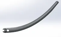
- Kickstand
Kickstand supports the chopper to rest it on the ground.
Features used to create it:
- Sketch: It is the base for making a 3D model which uses entities like line, Splines, ellipse etc to make a 2D representation of the part.
- Extrude boss: It is used to create 3D model out of a 2D sketch.
- Extrude cut: It is used to remove the material from the 3D model. Used for creating holes, paths etc by cutting the material in desired directions. It is basically the opposite of Extrude boss.
- Fillet: It is used to create both rounded inward or outward curves on edges.
- Loft: It is used to create complex geometry along two cross-sections like in here it is used between two ellipse and thus the created way is called lofted profile.
- Dome: The feature allows to create dome like structure on the faces it can be circular or elliptical.
- Split: It is used to project an entity on other surfaces
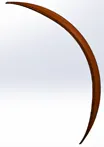
- Front Fender/ Rear Fender
Fenders are the protective mountings over the front and rear wheel.

Features used to create it:
- Sketch: It is the base for making a 3D model which uses entities like line, Splines, ellipse etc. to make a 2D representation of the part.
- Offset: Offset entities by a specified distance, allows to created adjacent parallel entities quickly and accurately.
- Trim entities: Allows to remove unwanted lines intersecting.
- Revolve: Taking the center line or axis it revolves the entity.
- Dynamic mirror: Makes the entity identical to the predefined sketch about its center.
- Split: It is used to project an entity on other surfaces.
- Appearances: Apply colors to the model.
- Chain
Used to transmit power from engine to the rear wheel, which is attached to a sprocket.
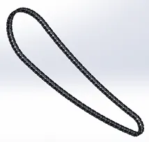
Features used to create it:
- Sketch: It is the base for making a 3D model which uses entities like line, Splines, ellipse etc. to make a 2D representation of the part.
- Trim entities: Allows to remove unwanted lines intersecting.
- Fillet: It is used to create both rounded inward or outward curves on edges.
- Block: Created in background to save time and adding blocks from tool and insert.
- Extrude boss: It is used to create 3D model out of a 2D sketch.
- Pattern: A curve driven pattern is used to cut short the time of adding blocks and extruding them one by one. The pattern can be used in open as well as closed loop.
- Appearances: Apply colors to the model.
- Oil Tank
A hollow container to store oil for chopper to run the engine.
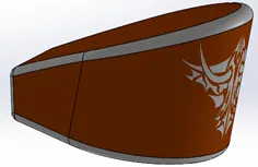
Features used to create it:
- Sketch: It is the base for making a 3D model which uses entities like line, Splines, ellipse etc. to make a 2D representation of the part.
- Extrude boss: It is used to create 3D model out of a 2D sketch.
- Combine: It is used to add or subtract two bodies with each other manually.
- Shell: Feature required to make a part hollow and thus defining the thickness of the shell. In this case the thickness of tank is 3mm.
- Fillet: It is used to create both rounded inward or outward curves on edges.
- Pedal
Used to rest the foot of the rider attached to the chassis.
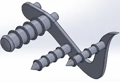
Features used to create it:
- Sketch: It is the base for making a 3D model which uses entities like line, Splines, ellipse etc. to make a 2D representation of the part.
- Extrude boss: It is used to create 3D model out of a 2D sketch.
- Fillet: It is used to create both rounded inward or outward curves on edges.
- Linear Pattern: Just like circular pattern it is used to pattern a part in linear direction.
- Dome: The feature allows to create dome like structure on the faces it can be circular or elliptical.
- Chamfer: Feature used to make a perfect square cut on the edges and corners.
- Front Wheel
Circular alloy block covered with rubber tire.
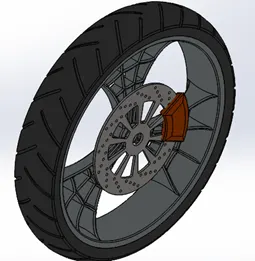
Features used to create it:
- Sketch: It is the base for making a 3D model which uses entities like line, Splines, ellipse etc. to make a 2D representation of the part.
- Revolve: Taking the center line or axis it revolves the entity.
- Trim entities: Allows to remove unwanted lines intersecting.
- Fillet sketch entity: Giving rounded end to edges and corners.
- Extrude boss: It is used to create 3D model out of a 2D sketch.
- Revolve: Taking the center line or axis it revolves the entity.
- Linear Pattern: Just like circular pattern it is used to pattern a part in linear direction.
- Chamfer: Feature used to make a perfect square cut on the edges and corners.
- Extrude cut: To create cavity in the part.
- Circular pattern: Feature used to create number of identical holes in circular pattern.
- Rear Wheel
Circular alloy block covered with rubber tire. A disc and sprocket is attached to the rear wheel, the engine transmits the power to the rear wheel.
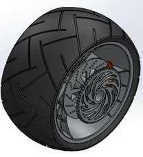
Features used to create it:
- Sketch: It is the base for making a 3D model which uses entities like line, Splines, ellipse etc. to make a 2D representation of the part.
- Revolve: Taking the center line or axis it revolves the entity.
- Trim entities: Allows to remove unwanted lines intersecting.
- Fillet sketch entity: Giving rounded end to edges and corners.
- Extrude boss: It is used to create 3D model out of a 2D sketch.
- Linear Pattern: Just like circular pattern it is used to pattern a part in linear direction.
- Chamfer: Feature used to make a perfect square cut on the edges and corners.
- Extrude cut: To create cavity in the part.
- Circular pattern: Feature used to create number of identical holes in circular pattern.
- Front Fork
Used to steer the bike.
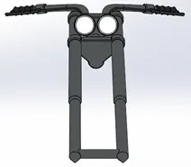
Features used to create it:
- Sketch: It is the base for making a 3D model which uses entities like line, Splines, ellipse etc. to make a 2D representation of the part.
- Trim entities: Allows to remove unwanted lines intersecting.
- Extrude boss: It is used to create 3D model out of a 2D sketch.
- Split: It is used to project an entity on other surfaces.
- Dome: The feature allows to create dome like structure on the faces it can be circular or elliptical.
- Mirror: Allows to create exact part quickly wrt the center reference plane.
- Projected curve: It allows to make complicated 2D curve by two different 2D curves its reference.
- Sweep: Allows to create 2D profile along with path given by 2D sketch.
- Chassis
The chassis is the frame of the chopper, all other components like engine, oil tank etc.
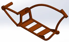
Features used to create it:
- Sketch: It is the base for making a 3D model which uses entities like line, Splines, ellipse etc. to make a 2D representation of the part.
- Trim entities: Allows to remove unwanted lines intersecting.
- Revolve: Taking the center line or axis it revolves the entity.
- Extrude boss: It is used to create 3D model out of a 2D sketch
- Extrude cut: To create cavity in the part.
- Dome: The feature allows to create dome like structure on the faces it can be circular or elliptical.
- Offset: Offset entities by a specified distance, allows to created adjacent parallel entities quickly and accurately.
- Fillet sketch entity: Giving rounded end to edges and corners.
- Mirror: Allows to create exact part quickly wrt the center reference plane.
- Projected curve: It allows to make complicated 2D curve by two different 2D curves its reference.
- Sweep: Allows to create 2D profile along with path given by 2D sketch.
- Circular pattern: Feature used to create number of identical holes in circular pattern.
- Split: It is used to project an entity on other surfaces.
- Composite curve: This feature combines two curves and make a single curve.
- Appearances: Apply colors to the model.
- Engine
Engine generates power to move the bike by converting chemical energy to heat and heat energy to rotational energy. This rotational energy of engine is transmitted to the rear wheel.
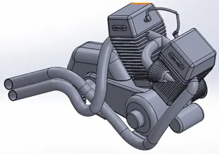
Feature used to create it:
- Sketch: It is the base for making a 3D model which uses entities like line, Splines, ellipse etc. to make a 2D representation of the part.
- Trim entities: Allows to remove unwanted lines intersecting.
- Revolve: Taking the center line or axis it revolves the entity.
- Extrude boss: It is used to create 3D model out of a 2D sketch
- Extrude cut: To create cavity in the part.
- Dome: The feature allows to create dome like structure on the faces it can be circular or elliptical.
- Offset: Offset entities by a specified distance, allows to created adjacent parallel entities quickly and accurately.
- Fillet sketch entity: Giving rounded end to edges and corners.
- Mirror: Allows to create exact part quickly wrt the center reference plane.
- Projected curve: It allows to make complicated 2D curve by two different 2D curves its reference.
- Sweep: Allows to create 2D profile along with path given by 2D sketch.
- Circular pattern: Feature used to create number of identical holes in circular pattern.
- Split: It is used to project an entity on other surfaces.
- Composite curve: This feature combines two curves and make a single curve.
- Appearances: Apply colors to the model.
- Gas tank
Used to store gas.
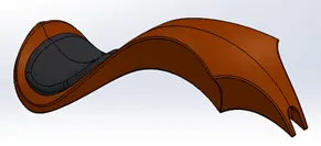
Features used to create it:
- Trim entities: Allows to remove unwanted lines intersecting.
- Projected curve: It allows to make complicated 2D curve by two different 2D curves its reference.
- Loft surface: surfaces generated by combining multiple 3D curve.
- Sweep surface: surfaces generated from a section curve positioned alone the path.
- Fill surface: A boundary is defined can be an edge, curve, line or composite curves to generate a surface path with any number of sides.
- Surface trim: Cuts away the material from a surface.
- Surface knit: Used to knit two free surface together, reduces the space between surface edges.
ASSEMBLY OF AMERICAN CHOPPER
Assembly requires establishing mates between different parts appropriately.
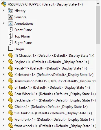
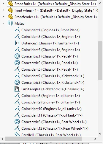
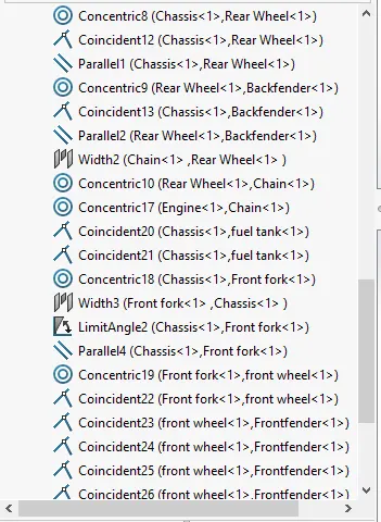
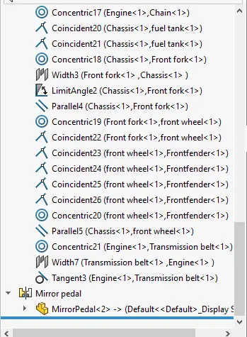
- First, the chassis is inserted and fixed. Now all other parts will be mated with respect to the chassis.
- Mates are applied to set all the parts on the bike.
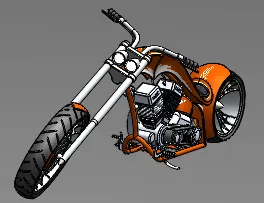
The following pictures denotes the sequences of adding the parts and applying mates to the American chopper assembly.
The following picture is the assembly pictures of American chopper in different view orientation.
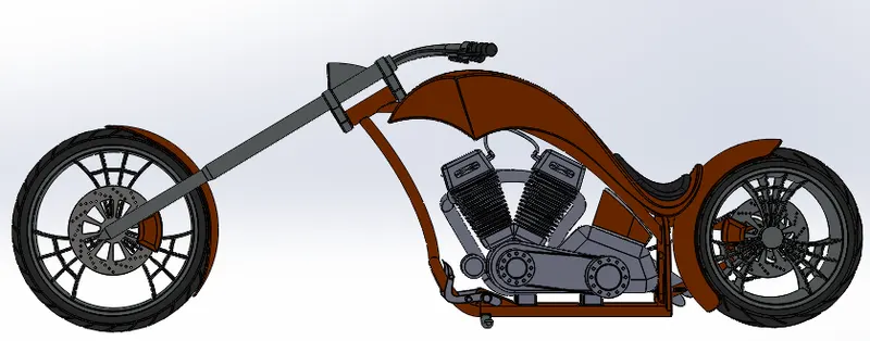
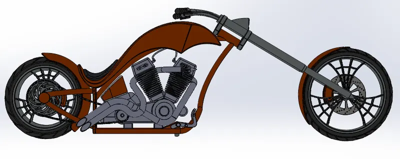
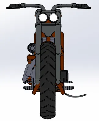
Camera view
Featured used for assembly:
- Inserting parts
- Mates: Mates give the relation between two parts, their orientation positioning and movement as required by the parts.
RENDERING
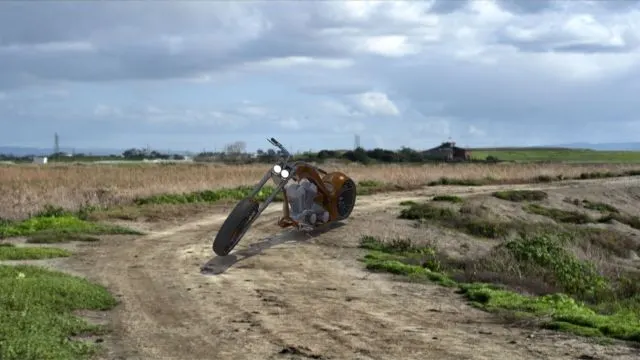
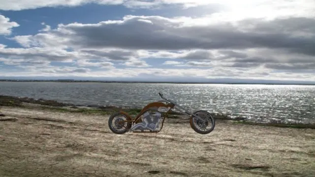
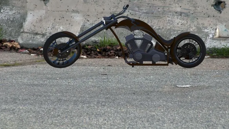
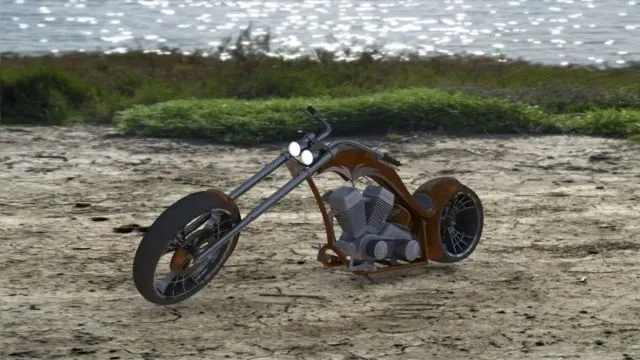
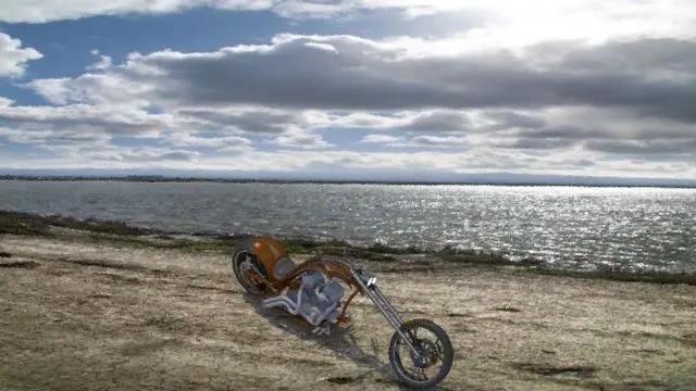
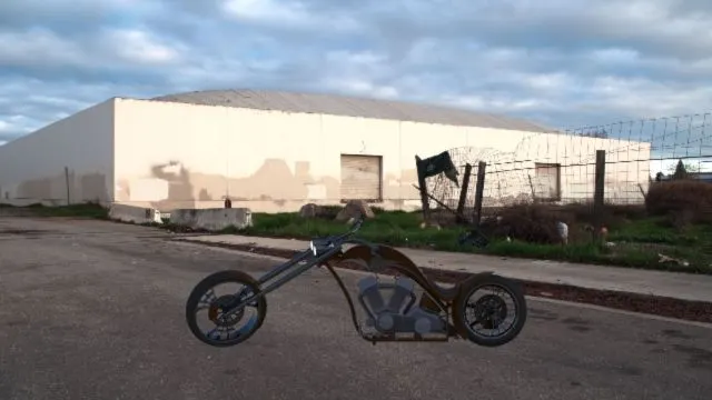
Rendering allows to give a photo-realistic perspective to the model created by Photoview 360.
Photoview 360 is a rendering tool inside the Solidworks to create photo-realistic model.
The following are some rendered photos created by photoview 360.
Camera view
American_chopper_render_nitin_dhariwal
CONCLUSION
- Creating parts of the model.
- Inserting and mating the parts to assemble the model.
- Finally rendering the model to give the model a realistic image using Photoview 360.