Radar Mast & Final Assembly of Yacht
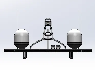
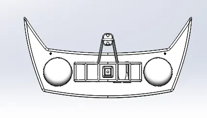
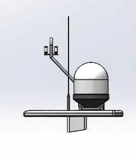
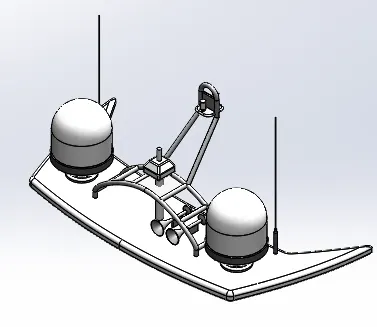
1 Radarmast
a. Front view
b. Top View
c. Left view
d. Isometric view
e. Feature tree
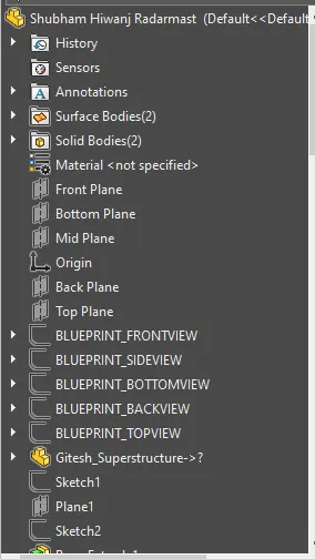
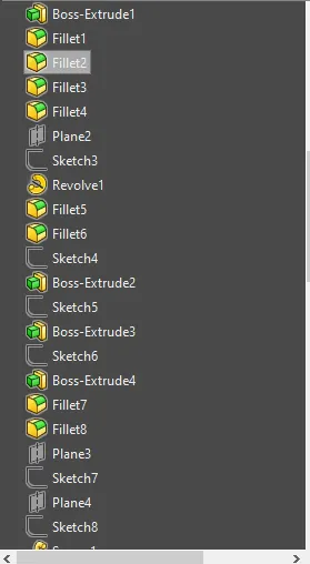
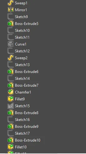
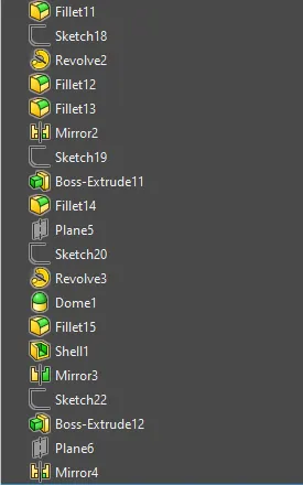
2. Yatch Assembly
TITLE: SURFACE MODELLING OF SUNSEEKER PREDATOR YACHT USING SOLIDWORKS
OBJECTIVE
Objective of this project to get detailed understanding of Surface Modelling using SOLIDWORKS. This project includes designing and modelling of each component of yacht followed by assembly. Rendering of final assembly using PHOTOVIEW 360 and SOLIDWORKS VISUALIZE.
INTRODUCTION
What is Surface Modelling?
Surface Modelling is the method of showing or presenting solid objects. The process requires you to convert between different 3D modelling types, such as converting the 3D object to show procedural surfaces, validate imperfections, and apply smoothness. While more complex than Wireframe Modelling, Surface Modelling is easier to achieve than Solid Modelling.
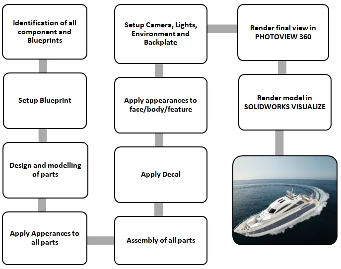
In this project, Sunseeker Predator Yacht is selected as base model to get understanding of Surface Modelling and Solid Modelling. Each Component of yacht designed, modelled and rendered using SOLIDWORKS. All modelled parts assembled together by applying proper and auto-fixed. Final model rendered using PHOTOVIEW 360 and SOLIDWORKS VISUALIZE to realistic view.
DESIGN METHODOLOGY
BASIC OF SOLIDWORKS
TERMINOLOGY
Following terms are used in solidworks for all parts and assemblies.
Plane: It is used for creating 2D sketch. It can be created on multiple direction to draw sketch for complex view.
Origin: It is a zero point in coordinate system. It helps to fully constrain the model or sketch.
Axis: It is as reference entity with multiple use in features like revolve, plane, pattern.
Face: It is a boundary of solid body or surface. It can be use to draw sketch on it.
Edge: It is line where two or more faces or surfaces are joined.
Vertex: It is an end point of line or edge.
TYPES OF TOOLS AND COMMANDS
SKETCH: It is basis for 3D modelling. It can create any default plane/new created plane/faces of feature/surfaces. Sketch can be created in 2D and 3D space.
SKETCH COMMANDS:
Smart Dimension: It is used to apply different dimensions like length, angle, diameter to entities of geometry.
Line: It used to create straight line with two end point. There are three options available Centreline, Midpoint and Line.
Circle: It is used create circle by two method i.e. Perimeter Circle and Centre Point Circle
Arc: It is used to create arc by method Centre Point Arc, Tangent Arc and Three Point Arc
Spline: It is a curve that passes through point specified by the user. Spline has provided with handle to operate shape require.
Fillet: It is used to apply fillet at intersection of drawn entities.
Trim Entities: It is used to remove unnecessary portion of geometry
Convert Entities: It is used to copy entities from different sketch. Also, it enables to copy edges of model to active sketch.
Offset Entities: It is used to copy entity on specified distance from original entity.
Sketch Picture: It is used to insert background image as blueprint for guide.
FEATURES: It used to create solid shape from one sketch. There are different types of design and shape can be achieved by using feature tools.
FEATURES COMMANDS:
Extruded: Extrude add or remove material by extruding one or more profiles. You can create extrude boss/bases, extrude cuts, or extrude surfaces. The extrude feature can be a solid, a thin feature, or a surface.
Revolved: Revolves add or remove material by revolving one or more profiles around a centerline. You can create revolved boss/bases, revolved cuts, or revolved surfaces. The revolve feature can be a solid, a thin feature, or a surface.
Swept Boss/Base: It sweeps a closed sketch along closed or open path to create solid feature.
Lofted Boss/Base: It enables to add material between two or more profile to create solid feature.
Fillet: It creates rounded internal or external face along one or more edges on solid feature or surface feature.
Chamfer: It creates beveled feature on selected edges, faces or a vertex.
Pattern Pattern repeats the selected features in an array based on a seed feature. You can create a linear pattern, a circular pattern, a curve driven pattern, a fill pattern, or use sketch points or table coordinates to create the pattern.
Reference Geometry: It helps to add new plane, axis, coordinate system for modelling.
Curve: It enables to create projected curve, split line, composite curve, helix and spiral.
Shell: It hollows out a part, leaves open the faces you select, and creates thin-walled features on the remaining faces. It creates closed hollow object with thin-walled when select solid object.
Mirror: It is very useful commands which helps to completely mirror faces, solid bodies, features about plane or face. Bunch of command work get mirror in one command. It fast modelling process.
Dome: It create dome shape on selected faces of solid feature.
Combine: It allows to combine two or more solid bodies to get one solid body.
Delete/Keep Body: This feature allows to delete or keep selected bodies.
Save Bodies: This feature allows to save bodies from part file as new part file.
SURFACES: Surfaces are a type of geometry that can be used to create solid features. It represents skin object which mean no thickness of object. It is used to get surface from two or more sketches. There are different types of complex and curvature solid model can be achieved by closed loop surfaces by using different tools.
SURFACES COMMANDS:
Swept Surface: It sweep profile along an open or closed path to create a surface feature.
Lofted Surface: It creates lofted surface between two or more profiles or sketches by specifying start and end constraint along a guide curves to control the path shape
Boundary Surface: The boundary surface feature lets us to create surfaces that can be tangent or curvature continuous in both directions (all sides of the surface). In most cases, this delivers a higher quality result than the loft tool.
Extruded Surface: Extrudes a sketch or selected sketch contours in one or two directions two create a surface feature.
Revolved Surface: Revolves a sketch or selected sketch contours around an axis to create a surface feature.
Filled Surface: Patches a surface within a boundary defined by edges, sketches, or curves. We can use constraint curves to fill surfaces and adjust resolution control to improve surface finish.
Ruled Surface: Inserts ruled surfaces in a specified direction from edges. Tangent to surface, Normal to surface, tapered to vector, perpendicular to vector or sweep can be selected. We can also trim and knit the surfaces and remove any connecting surfaces.
Trim Surface: It trims the surfaces where a surface intersects with another surface, a plane or a sketch
Knit Surface: It combines two or more adjacent, non-intersecting surfaces into a single surface body. The surfaces must joint at an edge. If the resulting knit surface encloses a volume, we can create a solid body from the Property Manager
Move/copy surface: Moves or copy surfaces about a plane or a sketch.
Offset Surface: Offsets surfaces using one or more contiguous faces. This tool helps us to create an offset surface with gaps.
Extend Surface: Extends one or more edges or faces on a surface, based on end conditions and extension type.
Mirror surface: A mirror feature is a copy of a selected feature, mirrored about a plane or planar face. A mirror sketches entity is a copy of a selected sketch entity that is mirrored about a centreline. If the original feature or sketch is modified, the mirrored copy is updated to reflect the change.
Thicken: Creates a solid feature by thickening one or more adjacent surfaces
DESCRIPTION
While designing, first we have to identify component or sub-assembly of Yacht to get final model assembly. Splitting component of a model before designing provide scope of improvement and avoid lengthy modelling.
BLUEPRINT SETUP
It is use as a guide for sketching and designing model. Before modelling of each part, blueprint setup to be done in part file. Sketch image of yacht is to be added to different plane as per view. It helps to draw and design model easily.
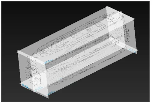
Fig 1. Blueprint Setup
COMPONENTS OF YACHT
- RADAR
- PROPELLER
- HULL
- GARAGE DOOR
- FRONT SEAT
- MIDDLE SEAT
- REAR SEAT
- SUPERSTRUCTURE
- RADAR MAST
- RADAR: Radaris a detection system that uses radio waves to determine the range, angle, or velocity of objects. It can be used to detect aircraft, ships, spacecraft, guided missiles, motor vehicles, weather formations, and terrain.
Command Used
- Line, Circle, Text. Point
- Extrude Boss/Base
- Extrude Cut
- Fillet
- Mirror
- Split Line
Modelling Procedure
- Part has symmetric geometry, so first create symmetric portion.
- Base feature (parent) created by drawing sketch and extruded boss feature
- Additional feature (child) added like cap and bolting by using extruded boss and extruded cut.
- The Radar has a circular slot underneath which was created using the extruded cut. This is very important while assembly to mate the part properly
- Fillet applied to edges of body and finally save the model by applying appearance.
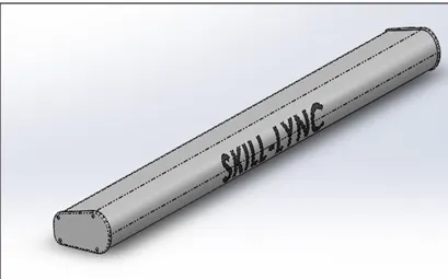
Fig 2. Solidworks Image
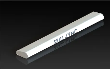
Fig 3. Rendered Image
- PROPELLER: A propeller is a device with a rotating hub and radiating blades that are set at a pitch to form a helical spiral, that, when rotated, performs an action which is similar to Archimedes' screw. It transforms rotational power into linear thrust by acting upon a working fluid, such as water or air. The rotationalmotion of the blades is converted into thrust by creating a pressure difference between the two surfaces. A given mass of working fluid is accelerated in one direction and the craft moves in the opposite direction.
Commands Used
- Line, Circle, Spline
- Revolve
- Extrude Cut
- Reference Geometry – Plane
- Loft
- Fillet
- Circular Pattern
Modelling Procedure
- Base feature (Parent) created by drawing sketch and revolved boss
- Create plane and draw sketch for blade. One blade of propeller created by lofted boss feature.
- Fillet added to blade outside edges and joint edges.
- Remove material from propeller shaft for mating by cut extrude feature.
- Use circular pattern to pattern blade of propeller by selecting blade as a feature and direction as edge or face of shaft.
- Apply the appearance and save the model.
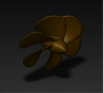
Fig 4. Solidworks Image
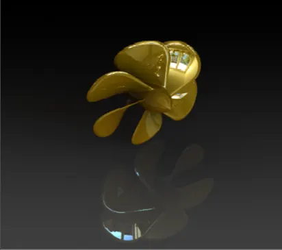
Fig 5. Rendered Image
- HULL: A hull is the watertightbody of a ship or boat. The hull may open at the top (such as a dinghy), or it may be fully or partially covered with a deck. Atop the deck may be a deckhouse and other superstructures, such as a funnel, derrick, or mast. The line where the hull meets the water surface is called the waterline.
Command Used
- Sketch Command used: Line, Circle, Spline, Rectangle, Ellipse, Straight Slot, Arc, Convert and Offset Entities, Trim Entities and 3D sketch.
- Features Command used: Extruded Boss, Revolved Boss, Swept Boss, Extruded Cut, Fillet, Chamfer, Linear Pattern, Circular Pattern, Shell, Mirror, Split, Delete/Keep Body and Save Bodies.
- Surfaces Command used: Extrude Surface, Revolved Surface, Swept Surface, Lofted Surface, Boundary Surface, Filled Surface, Offset Surface, Ruled Surface, Delete Face, Extend Surface, Trim Surface, Knit Surface, Thicken
- Reference Geometry: Plane
- Curve: Split Line, Project Curve, Composite Curve, Helix and Spiral
Modelling Procedure
- First open blueprint setup file and save as it by name Hull.
- Hull of yacht look like symmetric in geometry. It provides flexibility to create haft model then mirror it about plane or middle face of yacht.
- Main Body: Draw sketches to create two 3D curve by using project curve option
- Create three outer surface of hull using Loft Surface, Extrude Surface and trim unnecessary portions using Trim Surface. Combine three surface created surface by using Knit Surface.
- Fill the surface on top side and right side to make closed model using Fill Surface with edges of outside surfaces.
- Knit all surfaces to combine and select create solid to form solid model.
- Use shell to make deck for other components
- Windows: Use reference sketch, extruded cut, plane, swept boss, Fillet.
- Stair: Extrude cut, extruded boss, fillet
- Railing: Plane, reference sketch, project curve, swept boss, delete face, fillet
- Garage: Extruded cut, extruded boss, fillet, Save Bodies.
- Propeller Assembly: Revolved boss, extruded boss and cut, linear pattern, chamfer, fillet.
- Some additional feature added to hull to get good appearance.
- After modelling half portion of hull, mirror it along mid plane or middle face of hull.
- Create surface by using offset surface on deck and hide it. This surface will use for modelling Superstructure, Front Seat, Middle Seat and Rear Seat.
- Apply decal to floor, stair. Apply appearance to model and save it.
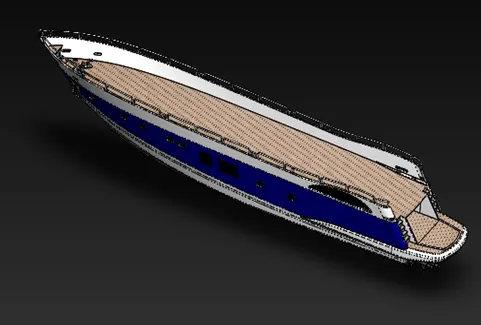
Fig 6. Solidworks Image
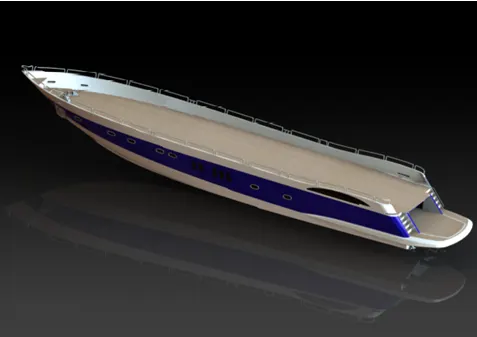
Fig 7. Rendered Image
- GARAGE DOOR: A garage door is a large door on a garage that opens either manually or by an electric motor (a garage door opener). Garage doors are frequently large enough to accommodate automobiles and other vehicles.
Command Used
- Extruded Boss
- Extruded Cut
- Shell
- Plane
- Mirror
- Fillet
- Text
Modelling Procedure
- Garage door need to be model in imported model from hull by cut extrude feature to get identical dimensions and proper fitting.
- Door is also symmetric body. So, first model half portion and then mirror it about plane.
- Shell feature use to thin the thickness of door.
- Cut extrude is use to add cut hole for mating in assembly.
- Fillet added to get smooth appearance.
- Apply the appearance and save the model.
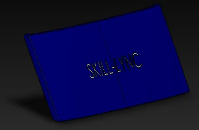
Fig 8. Solidworks Image
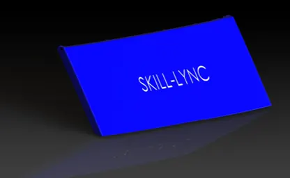
Fig 9. Rendered Image
- FRONT SEAT: Front Seat is located at the front end of Hull which is usually used for seating and to enjoy the scenery
Command Used
- Swept Surface
- Loft Surface
- Filled Surface
- Extrude Surface
- Trim Surface
- Knit Surface
- Revolved Boss
- Extruded Cut
- Fillet and Chamfer
- Mirror
- Dome
Modelling Procedure
- Open blueprint setup file and save as it by name Front Seat.
- Insert the Hull part by selecting the surface bodies.
- Create Swept Surface by creating a sketch on Deck face by drawing a spline & another sketch on created plane by drawing a line.
- Draw two lines and connect with previously created surface sweep and Extrude the surface.
- Trim the Extra surface and fill the gap portion with Filled Surface.
- Draw few sketches accordingly to trim extra surfaces.
- Create Surface loft using above two sketches.
- Trim the Extra surfaces & Knit it together.
- Draw lines accordingly to create seat and revolve it about 10 degree.
- Apply Fillets and mirror the bodies.
- Finally Apply Dome to seats & give appearance.
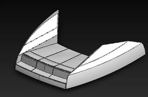
Fig 10. Solidworks Image
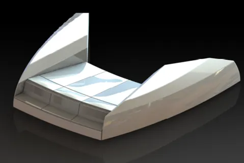
Fig 11. Rendered Image
- MIDDLE SEAT: Middle seat is situated at tail side of superstructure for seating.
Command Used
- Extrudes Boss
- Extrude Cut
- Mirror
- Chamfer
- Fillet
Modelling Procedure
- Open blueprint setup file and save as it by name Front Seat.
- Insert the Hull part by selecting the surface bodies.
- Middle seat looks like symmetric model. So, it can be created with half body and then apply mirror feature.
- Draw L shape sketch on deck surface and extrude it to get bottom structure of seat.
- Create rectangle sketch on new plane for seat and extrude it.
- Create back support by using extrude feature
- Apply Fillets and mirror the bodies.
- Create sketch for table base at front of seat. Draw sketch on face feature to get table support and extrude it. Then draw sketch of table plate and extrude it.
- Finally apply appearance.
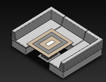
Fig 12. Solidworks Image
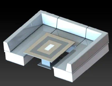
Fig 13. Rendered Image
- REAR SEAT: Rear seat is situated at tail side of hull.
Command Used
- 3D Sketch
- Reference Plane
- Swept Surface
- Loft Surface
- Offset Surface
- Extend Surface
- Extrude Surface
- Trim Surface
- Knit Surface
- Extrude Boss
- Revolved Boss
- Extruded Cut
- Fillet and Chamfer
- Mirror
- Swept Boss
Modelling Procedure
- Open blueprint setup file and save as it by name Front Seat.
- Insert the Hull part by selecting the surface bodies.
- The main body of the Rear Seat is modelled using Swept Surface, Off-set Surface and the remaining portion is trimmed using Trim Surface tool.
- By using the Reference Plane, the Seats are created with the help of Lofted Surface, Surface Trim and Extended Surface.
- The Flag Post is created using Revolved Boss/Base and the Flag was created by drawing the required 3D sketch and then the 3D sketches lofted to form the Flag.
- The Tail Lamps created by using Extruded Boss/Base, Fillets and Mirror tool.
- The Steel Gates for Stairs designed by using the reference plane and the Swept Surface.
- To remove the gaps the all the Surfaces must be Knitted together using Knit Surface.
- The required fillets and chamfer applied before mirroring the second half using Mirror tool and after mirroring fillet applied to remaining.
- Finally, save the part by adding appropriate appearances.
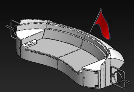
Fig 14. Solidworks Image
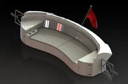
Fig 15. Rendered Image
- SUPERSTRUCTURE: A superstructure is an upward extension of an existing structure above a baseline. It is an extended construction of any building or platform that rises above the rest of the building or platform in a distinct manner.
Command Used
- 3D Sketch
- Reference Plane
- Swept Surface
- Loft Surface
- Offset Surface
- Extend Surface
- Extrude Surface
- Trim Surface
- Knit Surface
- Extrude Boss
- Revolved Boss
- Extruded Cut
- Fillet and Chamfer
- Mirror
- Swept Boss
Modelling Procedure
- Open blueprint setup file and save as it by name Front Seat.
- Insert the Hull part by selecting the surface bodies.
- The side surface of the superstructure is created by using extruded surface, lofted surface, filled surface, trim surface and knit surface.
- The front side of the superstructure was designed to have four rest beds which were created using extruded boss/base, fillets and dome.
- The front edge of the superstructure was provided with a water feature which was created using extruded boss/base, extruded cut, and filled with a water appearance.
- The windshield created by extruded cut and the wipers were created by using 3d sketch and reference plane with the help of swept boss/base.
- The portholes for the superstructure were created by using extruded surface, trim surface and extend surface.
- ruled surface used to fill the left-out edges.
- The back doors of the superstructure created using extruded cut, fillets and reference plane.
- Then all the surfaces generated were knitted together to form a solid body.
- The superstructure consists of two surface bodies and five solid bodies.
- One of the surfaces was the deck surface the other one was used to place the radar mast so it was renamed as radar mast reference surface.
- Then the other half model mirrored and the apply fillets
- Apply the appearances and finally the save the part.
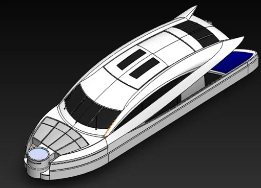
Fig 16. Solidworks Image
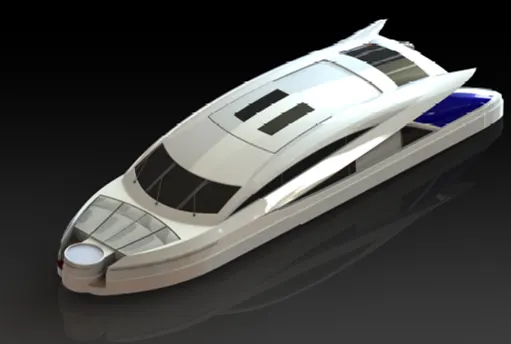
Fig 17. Rendered Image
- RADAR MAST: A mast is a pole that rises vertically from a ship and supports the sails. The mast of a sailing vessel is a tall spar, or arrangement of spars, erected more or less vertically on the centre-line of a ship or boat. Its purposes include carrying sails, spars, and derricks, and giving necessary height to a navigation light, loo-out position, signal yard, control position, radio aerial, or signal lamp. Large ships have several masts, with the size and configuration depending on the style of ship. Nearly all sailing masts are guyed.
Command Used
- Extrude Boss
- Revolved Boss
- Swept Boss
- Mirror
- Chamfer and Fillet
- Plane
- Shell
- Project Curve
Modelling Procedure
- Open blueprint setup file and save as it by name Front Seat.
- Insert the Superstructure part by selecting the surface bodies option.
- Create a sketch on surface of radar mast by drawing a horizontal line from surface and apply fillets to outer and inner edges.
- Draw 4 splines and a line as per Blueprint and extrude it on created plane.
- For Radar Indicators - Draw a sketch on top face of previous extrude using a line and 3-point arc., revolve it. Draw a circle on extruded face and extrude it and apply fillets.
- Antenna: Create a Sketch on Extrude1 face by drawing a circle and extrude it. Draw one more circle on extruded face and extrude it. Create one more extrude on previous extrude face by drawing a circle.
- Create a sweep by drawing a sketch on created plane using spline and a circle on 3D sketch.
- Mirror above sweep across Plane 2 and connect them by drawing three circles on sweep and extrude them.
- Create a Projected curve as per requirement by drawing sketches on respective Planes.
- Create a Sweep by drawing a circle at the edge of projected curve.
- Horn: Draw few lines and splines as per blueprint. Use revolved boss and apply dome to one end and shell to another end.
- Mirror Everything except Horn across Mid Plane.
- Horn Support: Draw a straight slot on extrude 1 face and extrude up to horn face.
- Create a Plane using above extruded right face and offset it. Mirror the Horn and its support across the created plane.
- Finally apply the appearance to Radar Mast, Antenna, Horn & Indicators.
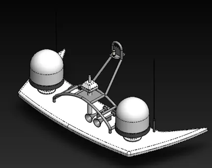
Fig 18. Solidworks Image
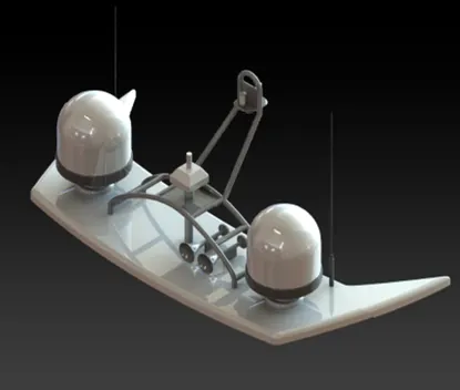
Fig 19. Rendered Image
ASSEMBLY
All parts of yacht have been modelled. Hull is the main structure of yacht. Some parts are modelled using some references from Hull. So, because of references there is no need to add mating relations to these parts. It will be automatically fixed with Hull.
But some parts are individually modelled. So, there should be proper mating relation as per their characteristics.
Mates Used
- Coincident: This mate use to aligned object at same positions.
- Concentric: This mate allows to aligned object radially.
- Distance: Distance mate use to aligned object at some distance.
Assembly Procedure
- To start assembly, open new assembly file.
- Insert Hull Part and click ok. It gets automatically fixed in assembly with plane.
- Then insert Superstructure, Front Seat, Middle Seat accordingly.
- Insert Radar Mast and click ok. It gets automatically fixed with Superstructure.
- Insert Rear Seat and click anywhere in the space to add relation manually. Use Distance mates to fixed rear seat at back side of deck surface.
- Insert Garage Door and apply concentric mate with garage hall support shaft.
- Insert propeller and apply concentric mate with transmission shaft.
- Insert Radar and apply concentric mate with radar mast shaft.
- Insert Pre-modelled American Chopper assembly and apply coincident mate with mid plane of hull.
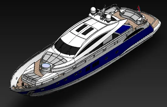
Fig 20. Solidworks Image
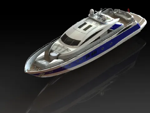
Fig 21. Rendered Image
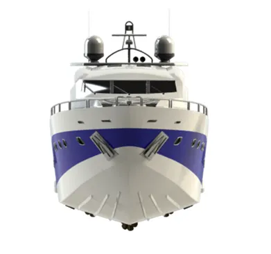
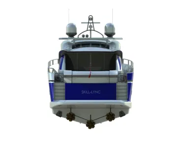
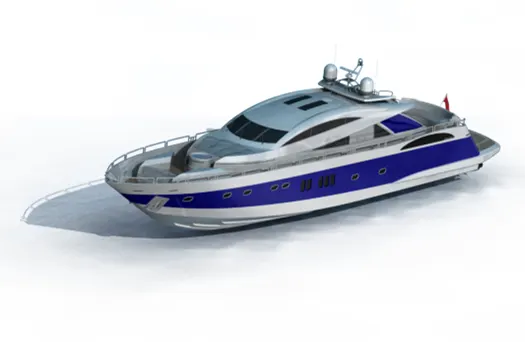
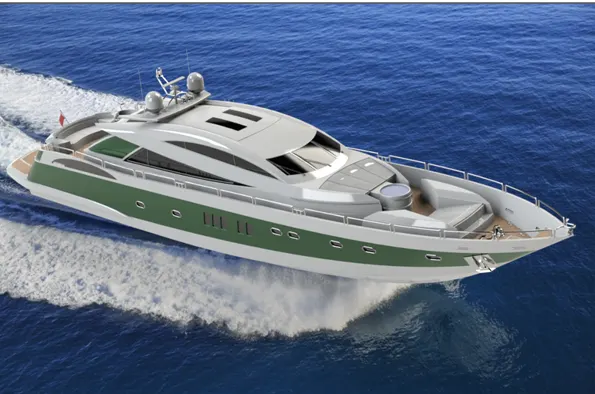
RENDERING
- Rendering is the process of creating realistic image model in real world environment.
- Rendering can be done two ways in solidworks.
- Photoview 360
- Solidworks Visualize
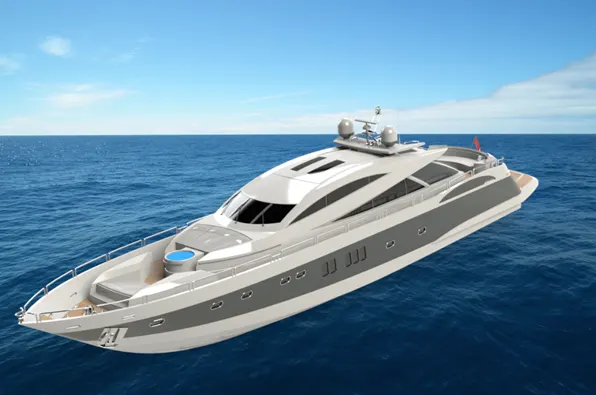
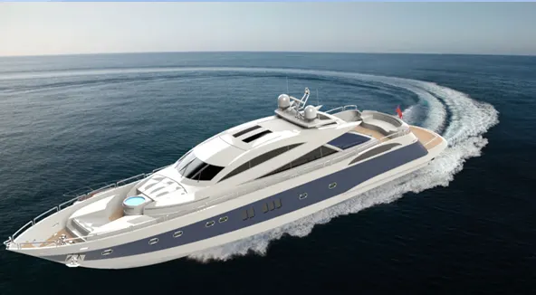
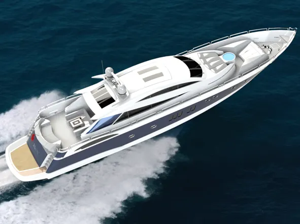
Following are images of rendering in Photoview 360.
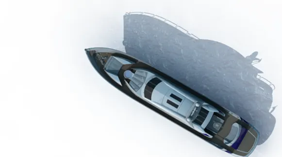
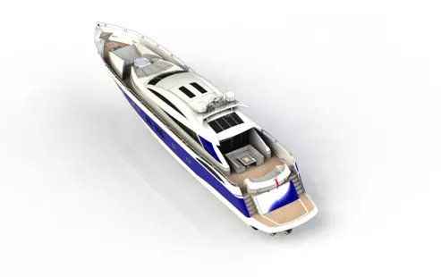
Following are images of rendering in Solidworks Visualize.
Conclusion
- Part modelling of American chopper using Surface Modelling tools in Solidworks
- Understanding of features and flexibility of modelling in Solidworks
- Part is assembled together to get complete assembly in Solidworks
- The realistic image generates in Photoview 360 and Solidworks Visualize