Photo Realistic Rendering
TITLE: MODELLING AND RENDERING OF AMERICAN CHOPPER USING SOLIDWORKS
OBJECTIVE:
Create 3D model of American Chopper by using SOLIDWORKS 2020.
Create model of different sub-assemblies od chopper using solidworks.
Assembly of model parts to get final model.
Rendering final model to get Photorealistic model using Solidworks Photoview 360 or Solidworks Visualize.
INTRODUCTION
Designing of any object start with modeling 2D and 3D images. There are multiple software’s available to get 2D and 3D model of object. 2D modeling is process of representing different view of physical body in space. 3D modeling is process of representing a physical body using collection of points in 3D space. Part modeling consists of both processes while designing any object. In Part Modeling you can create a part from a conceptual sketch through solid feature-based modeling, as well as build and modify parts through direct and intuitive graphical manipulation. This project consists of sketching, featuring and part modeling different parts of American chopper with the help of Solidworks 2020. Rendering the final assembly with help of Solidworks Photo view 360 or Solidworks Visualize.
WHAT IS SOLIDWORKS?
Solidworks is a 3D modeling software (CAD/CAE) which is used to model a product and perform analysis to check its behaviour in real world. It is developed by DASSAULT SYSTEMS.
DESIGN METHODOLOGY
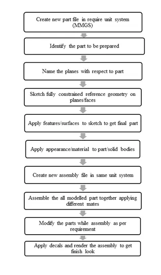
DESCRIPTION
Part creation process start from drawing fully defined 2D sketches. These sketches are the references to multiple features/surfaces by which 3D part created.
Sketch
Sketch consists of various options for creating different entities. Some of these as per follow,
- Line
- Circle
- Polygon
- Spline
- Offset
- Fillet
- Convert Entities
- Trim Entities
There are different ways available to use above options.
- Features and Surfaces
These tabs consist of multiple options which can help to create different shape solid body and surfaces. All require options will discuss in each part modeling of American Chopper.
- Appearance
In this feature, we can apply material or visual appearance to part or model. These appearances help us while rendering to Achieve real world image.
American Chopper
American chopper consists of 13 parts/sub-assemblies as per below.
- Transmission Belt
- Kickstand
- Front Fender
- Rear Fender
- Front Wheel
- Rear Wheel
- Pedal
- Chain
- Gas Tank
- Oil Tank
- Front Fork
- Chassis
- Engine
1) TRANSMISSION BELT: Transmission belt in the chopper is used to transmit the power from engine to gearbox.
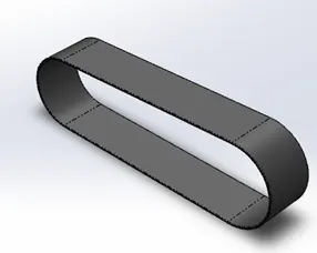
Feature used to create Transmission Belt
- Extrude: This feature is used to convert 2D sketch into 3D object.
- Fillet: This feature is used to convert external and internal edges into rounded shape.
- Offset Entities: offset option is used to create same entities on some distance or to create loop of entities.
Procedure
- First draw the fully defined sketch of require dimension on front plane using line and arc option. Then offset the sketch on Some distance to create thickness of belt.
- Then extrude command is used to convert 2D sketch into 3D.
- Fillet is applied as per requirement to sharp edges.
- Model is ready to save.
2) KICKSTAND: It is use to support to chopper when not in use and pivoted to chassis in such way that it can be move down the frame.
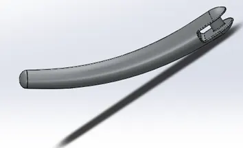
Feature used to create Kickstand
- Extrude Boss: This feature is used to convert 2D sketch into 3D object.
- Fillet: This feature is used to convert external and internal edges into rounded shape
- Loft: Determines the profiles used to create a loft. Select sketch profiles, faces, or edges to connect. Lofts are created based on the order of profile selection.
- Dome: This feature is use to apply dome shape to faces. You can apply domes to faces whose centroid lies outside the face. This allows you to apply domes to irregularly shaped contours.
- Split: This feature is use to split the solid bodies, surfaces and allow us to remove unnecessary portion.
- Extrude Cut: It help to remove the material from solid bodies.
3) FRONT FENDER: It is mounted on front wheel and below the front fork. It prevent mud particle being thrown into the air by rotating tyres.
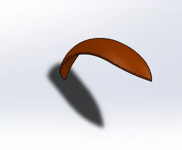
Feature used to create Front Fender
- Revolve: Any profile or multiple profile can be revolved about an axis, centre line or edges and obtain solid bodies from 0degree to 360 degree.
- Dynamic Mirror: With this feature any sketch or entities can be mirror about pre-selected entity or sketch.
- Split
- Offset Entities
4) REAR FENDER: The use of rear fender same as front fender. It is mounted on chassis above the rear wheel.
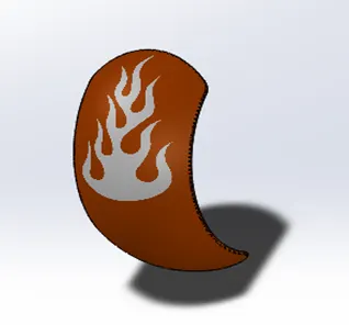
Feature used to create Rear Fender
- Shell: This feature hollows out part, leaves open the faces selected and creates thin walled feature on remaining faces. Also, it creates closed hollow model.
- Revolve
- Split
- Fillet
5) FRONT WHEEL
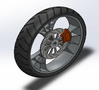
Feature used to create Front Wheel
- Combine: It allows combining two or more solid bodies.
- Circular Pattern: It is use to pattern the feature circular at require instances.
- Chamfer: It creates sloping surface at solid bodies’ corner or edges.
- Extrude Boss
- Extrude Cut
- Revolve
6) REAR WHEEL
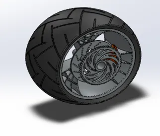
Feature used to create Rear Wheel
- Combine: It allows to combine two or more solid bodies.
- Circular Pattern: It is use to pattern feature circular at require instances.
- Chamfer: It creates sloping surface at solid bodies’ corner or edges.
- Extrude Boss
- Extrude Cut
- Revolve
7) PEDAL: It is attached to chassis to rest rider's foot while driving.
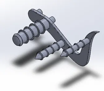
Feature used to create Pedal
- Linear Pattern: This pattern is same like circular pattern. But it works like its name linearly along a line, centerline or edge atRequire instances.
- Revolve
- Extrude Boss
- Fillet
- Dome
- Chamfer
8) CHAIN: It is part of transmission system. It helps to transmit power from engine to rear wheel with the help of sprocket mounted on rear wheel and engine.
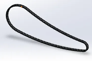
Feature used to create Chain
- Curve Pattern: It allow to pattern solid bodies along a curve path at require instances.
- Block: Sometime we need a single sketch multiple times. We can convert such a sketch into block at add it whenever Require.
- Mirror
- Extrude
- Fillet
Procedure to create Block
- Create sketch
- Click makes Block. (Block toolbar) or Tools>Block>Make.
- Select sketch to convert into block and save it.
9) GAS TANK: It is used to store gas require to start engine.
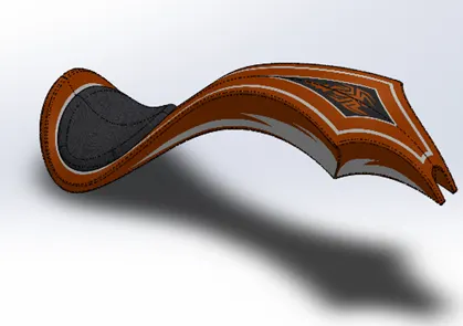
Feature used to create Gas Tank
- Sweep Surface: It generate surface from section curve positioned along a path.
- Loft Surface: It create surfaces between existing edges by creating smooth tangency between selected curve.
- Extrude Surface: It convert projected surface into 3D surface.
- Boundary Surface: This feature create surface between boundaries or edges but specifying both direction.
- Surface Knit: This feature is use to combine two or more surfaces to make one solid surface.
- Surface Trim: It is use to remove unnecessary surface.
- Sweep Cut: It is used cut solid bodies along a path.
- Fillet
- Shell
- Mirror
10) OIL TANK: It is used to store oil require for engine
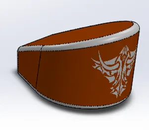
Feature used to create Oil Tank
- Extrude
- Combine
- Fillet
- Shell
11) FRONT FORK: It is a handling system of bike. It is connected between chassis and front wheel.
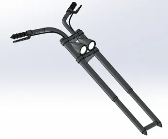
Feature used to create Front Fork
- Project Curve: It help to get 3D curve which is projected on the basis of two 2D sketches.
- Sweep: This feature creates solid body from 2D sketch profile along a 3D curve.
- Move/Copy: It help to move/copy any object.
- Mirror: It help to mirror half portion of fork to complete the fork.
- Extrude
- Combine
- Revolve
- Fillet
- Plane
- Dome
- Linear Pattern
12) CHASSIS: It is a load bearing framework. It forms a skeleton of chopper which support to all part of bike like engine, front Fork, wheel etc.
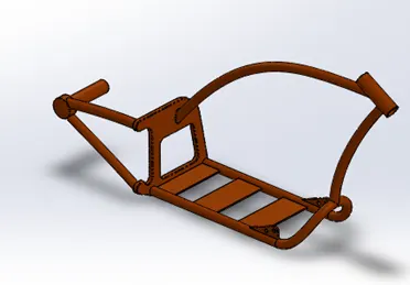
Feature used to create Chassis
- Project Curve
- Sweep
- Mirror
- Extrude
- Combine
- Revolve
- Fillet
- Plane
- Dome
- Split
13) ENGINE: It is a heart of bike which is use to run the chopper. it converts chemical energy into mechanical work
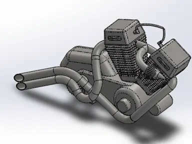
Feature used to create Engine
- Composite Curve: It help to combine two 3D curve
- Extrude Cut
- Plane
- Offset
- Circular Pattern
- Linear Pattern
- Sweep
- Mirror
- Project Curve
- Extrude
- Combine
- Revolve
- Fillet
- Plane
- Dome
- Split
Assembly of American Chopper
To start assembly, we have to load new assembly file.
While assembly, we need to insert each part step by step followed by mating relations to each other.
Feature used for assembly
- Insert Part
- Mates
- Mirror
Whereas,
Mates: It is use to provide relation between part as per their working principle. We have to define the mates as per present
condition and whatever look we require.
Following are the relations used in mates:
- Coincident
- Parallel
- Concentric
- Angle
- Tangent
- Width Mate
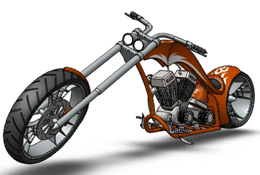
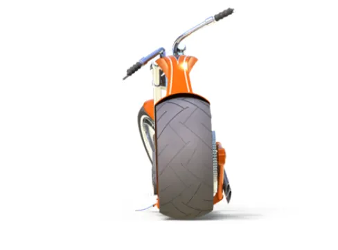
Photo Realistic Rendering
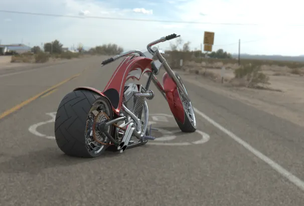
Rendering is the process of creating realistic image model in real world environment.
Rendering can be done two ways in solidworks.
- Photoview 360
- Solidworks Visualize
Following are rendered images in Photoview 360
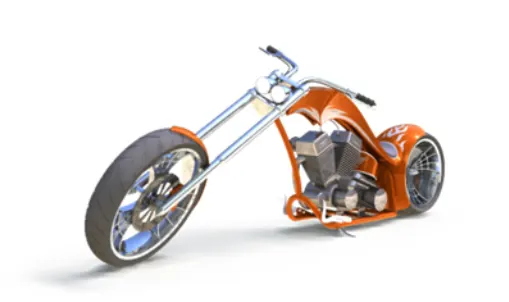
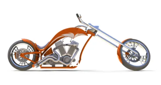
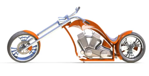
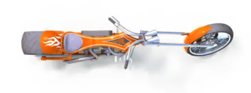
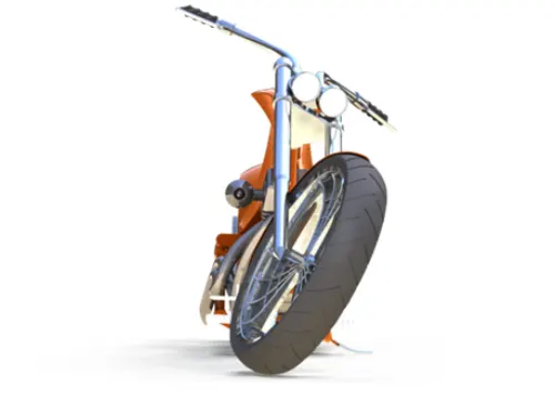
Rendered image in Solidworks Visualize
Conclusion
- Understanding of user interface of Solidworks.
- Part modelling of American chopper using solid modelling tools in Solidworks.
- Understanding of features and flexibility of modelling in Solidworks.
- Part is assembled together to get complete assembly in Solidworks.
- The realistic image generates in Photoview 360 and Solidworks Visualize.