Modeling and Photorealistic Rendering of Sunseeker Predator Yacht
MODELLING OF SUNSEEKER PREDATOR YACHT
OBJECTIVE:
- To model the different parts of a Sunseeker Predator Yacht using the solid and surface modelling tools.
- To assemble the individually modelled parts of the Sunseeker Predator Yacht.
- To use Photoview 360 and Solidworks Visualize to perform a photo realistic rendering of the Sunseeker Predator Yacht.
INTRODUCTION:
A yacht is a sail or power vessel used for pleasure, cruising, or racing. There is no standard definition, so the term applies to such vessels that have a cabin with amenities that accommodate overnight use. To be termed a yacht, as opposed to a boat, such a pleasure vessel is likely to be at least 33 feet (10 m) in length and may have been judged to have good aesthetic qualities.
Solidworks is a Computer Aided Design (CAD) and Computer Aided Engineering (CAE) computer program published by Dassault Systemes. It is one of the prominent modelling software available in the market. The parts of the Sunseeker Predator Yacht are modelled using Solid modelling and Surface modelling tools. All the parts of the Sunseeker Predator Yacht are then imported to the Assembly workspace and the final assembly of the Yacht is done by adding the required mates. Photoview 360 and Solidworks Visualize are used to obtain the rendered images of the assembled Sunseeker Predator Yacht.
DESIGN METHODOLOGY:
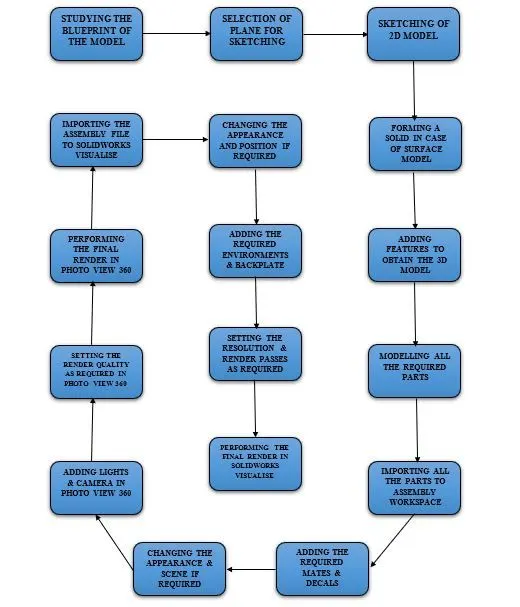
DESCRIPTION:
- PROPELLER:
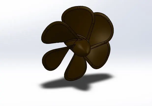
OPERATIONS:
- Sketch the profile as per the required dimensions using Line and Arc
- Constrain the sketch by adding Relations and Smart Dimension.
- Use Revolve tool to revolve the sketch.
- Create a new Plane.
- Draw two sketches using the Rectangle tool for the given dimensions.
- Use Surface Loft and connect the two sketches to create the blades of the propeller.
- Provide the required Fillets to create a curvature on the ends of the blades.
- Create a circular sketch and Cut-Extrude it to create a hollow opening for the propeller to attach with the shaft.
- Add Fillets as required and pattern the blades around the propeller using Circular Pattern
- Finally, change the Appearance as required.
- RADAR:
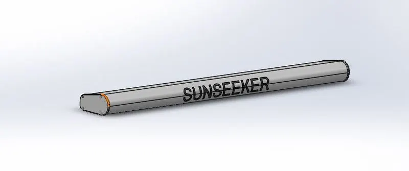
OPERATIONS:
- Draw a sketch using Line
- Extrude the sketch using Boss-Extrude.
- Add Fillets as required.
- Draw another three sketches and Boss-Extrude and then Cut-Extrude them to create a riveted joint.
- Pattern the riveted joints using Sketch Pattern tool.
- Mirror the whole radar.
- Create a hole at the bottom of the radar using Cut-Extrude
- Custom text is engraved on the radar using Split Line
- Fillets and Appearances are added as required.
- HULL:
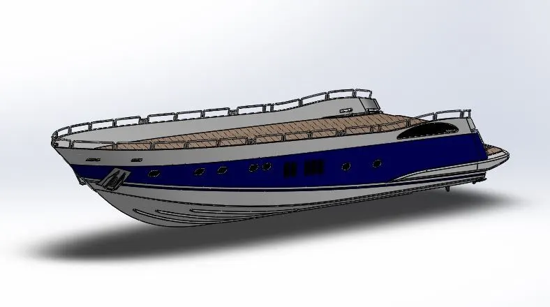
OPERATIONS:
- Blueprints are imported into the part area using Sketch Picture
- Additional Planes are created as required.
- The top and bottom side edges of the hull are sketched with the help of blueprint using the Project Curve
- The surfaces between these curves are filled using Surface Loft
- The extra surface is removed using Surface Trim
- A sketch is drawn and extruded using Surface Extrude.
- The extra surfaces are removed using Surface Trim
- The surfaces are then knitted using Surface Knit
- The surface of the top deck and the mid portion of the hull are filled using Surface Fill
- Shell tool is used to create a equal thickness around the surface of the hull.
- Then, the top deck is created using Boss-Extrude
- Windows, anchor holes and port holes are created using Cut-Extrude and Sweep
- Pathway for staircase is created using Cut-Extrude.
- The stairs are created using Boss-Extrude.
- The anchor holder and support cables are created using Boss-Extrude, Sweep, Dome, Revolve, Linear Pattern, Helix & Spiral and Cut-Extrude
- The side railing for the hull is made using Sweep and Project Curve
- The stabilizer and the shaft for the propeller are made using the Boss-Extrude, Revolve, Cut-Extrude and Linear Pattern
- Using the Split tool, the garage door is removed and is kept for later use.
- The body of the hull is combined using Combine tool.
- The Mirror tools is used to mirror the other part of the hull to get a complete part.
- Fillets, Chamfers and Appearances are added as required.
- GARAGE DOOR:
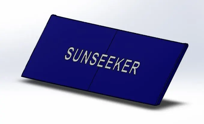
OPERATIONS:
- The part from the hull portion is used as a result of Split
- The extra portions are removed using Cut-Extrude
- Shell tool is used to give equal thickness on the surface.
- A hole for the garage door to join with hull is created using Cut-Extrude
- Fillets and Chamfers are added as required.
- The door is mirrored using Mirror tool to get the complete structure of the door.
- Custom text is engraved on the door surface as required using Cut-Extrude
- Appearances are added as desired.
- FRONT SEAT:
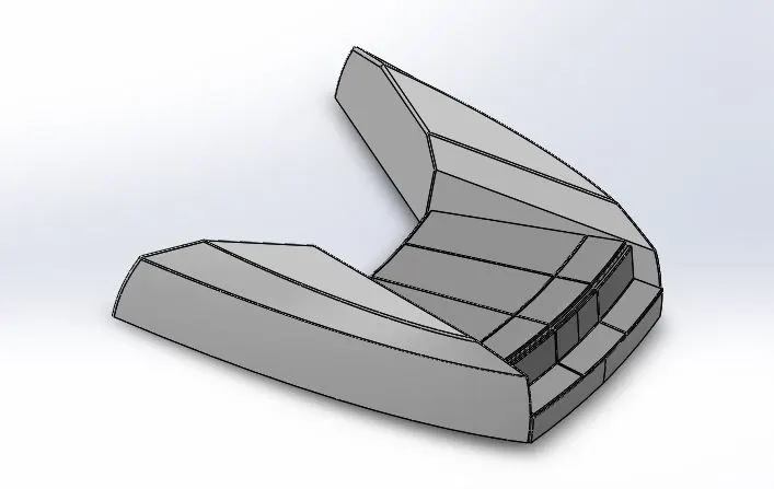
OPERATIONS:
- The hull reference is imported using the Insert à Part
- A side surface structure for the front seat is created using Surface Sweep, Surface Extrude, Surface Trim, Surface Fill, Surface Loft and Surface Knit
- The seats and mattresses are created using the Revolve tool and mirrored using the Mirror
- Dome tool is used to give a bulge on the mattress.
- Fillets, Chamfers and Appearances are added as required.
- MIDDLE SEAT:
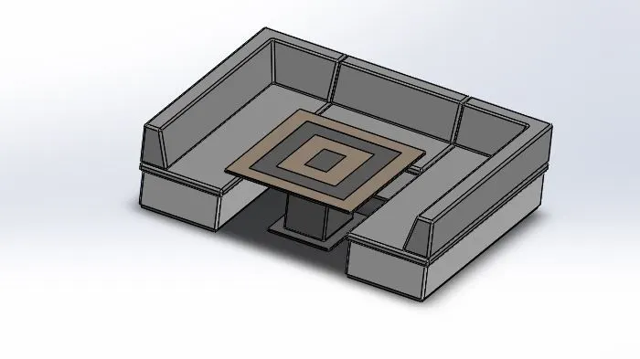
OPERATIONS:
- The hull reference is imported using the Insert à Part
- The bottom and seat parts are created using Boss-Extrude.
- Add Chamfer as required on the seat to create a reclining position.
- Mirror the seats.
- Create the base, middle and top parts of the table using Boss-Extrude
- Add Fillets as required.
- Add Appearances as required.
- REAR SEAT:
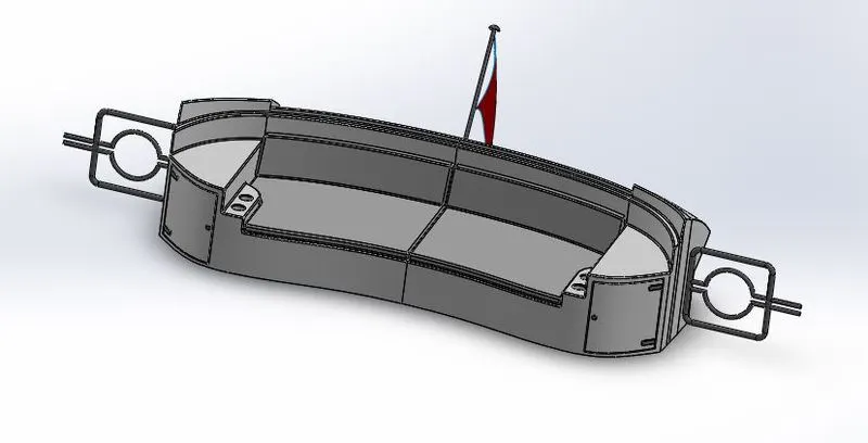
OPERATIONS:
- The hull reference is imported using the Insert à Part
- For the required profile, draw a sketch and use Surface Sweep tool to create the outer surface of the seat.
- Using Surface Offset, Surface Trim, Ruled Surface, Surface Knit, Surface Extend and Surface Loft tools the outer surface of the middle seat is designed.
- The seats as well as the locks and hinges for the cupboard are made using the Boss-Extrude and Cut-Extrude
- Create two cup holders using Cut-Extrude.
- Add Fillets and Chamfer wherever required.
- Create the two railings using Sweep and Mirror
- Create a flag staff using Revolve
- Create a flag using 3D Sketches and Surface Loft
- Add Appearances as required.
- SUPER STRUCTURE:
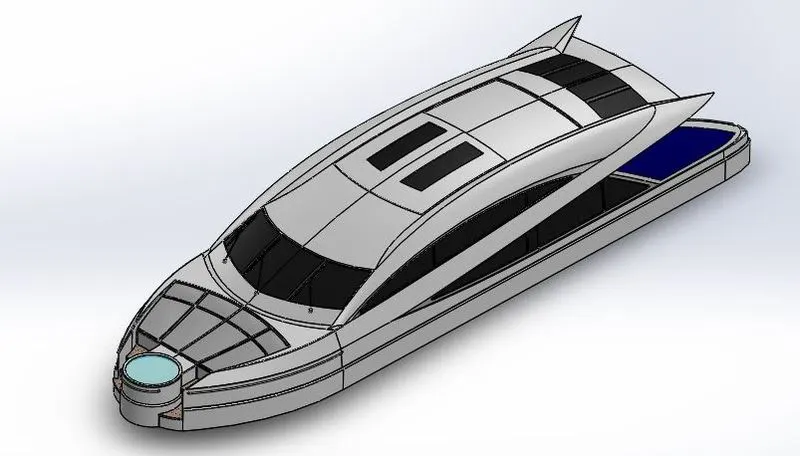
OPERATIONS:
- The hull reference is imported using the Insert à Part
- The surface of the super structure is created using Surface Extrude, Surface Sweep, Ruled Surface, Surface Trim, Surface Loft, Surface Fill and Project Curve
- They are then knitted using Surface Knit
- Create the jacuzzi water line using the Boss-Extrude and Cut-Extrude
- Create the jacuzzi staircase using Surface Extrude, Surface Trim, Surface Extend and Surface Sweep
- Create a doorway using Cut-Extrude
- Create window panels on the top of the super structure using Boss-Extrude and Cut-Extrude
- Mirror the body to get the complete super structure of the yacht.
- Add wipers and connecting rods using Boss-Extrude, Cut-Extrude and 3D Sketch tools.
- Add a reference for radar mast using Offset Surface
- Chamfer and Fillets are added as required.
- Appearances and Decals are added as required.
- RADAR MAST:
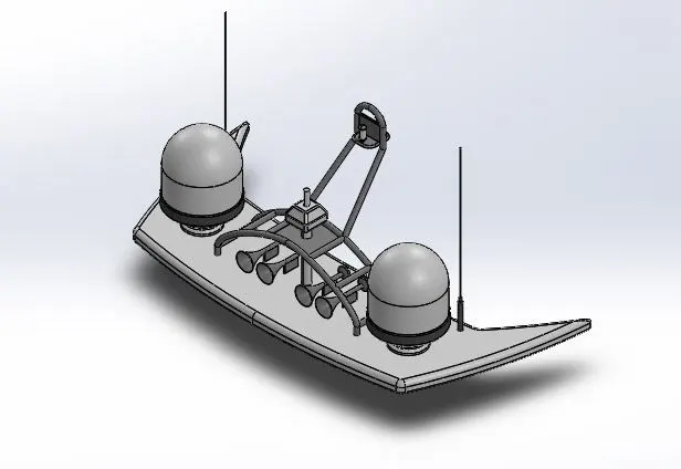
- The hull reference is imported using the Insert à Part
- Sketch the base of the radar mast and extrude it using Boss-extrude.
- The radar is created using Revolve
- Antenna is created using Boss-Extrude
- Mast is created using Sweep, Projected Curve and Boss-Extrude
- The mast is then mirrored using Mirror
- The lights on the mast are created using Revolve tool and mirrored to the other side.
- Horn is created using Revolve, Dome, Shell and Boss-Extrude It is then mirrored.
- All the bodies are combined using Combine tool and are mirrored using Mirror
- Chamfer and Fillets are added as required.
- Appearances are added as required.
- ASSEMBLY:
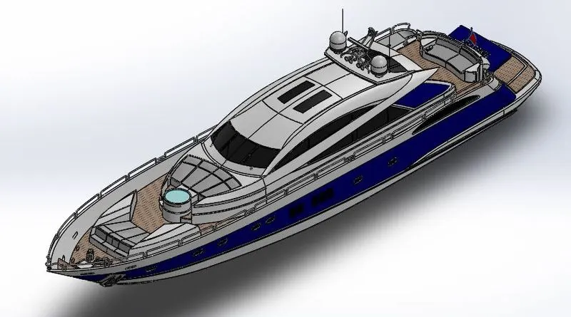
OPERATIONS:
- The hull part file is first imported into the Solidworks Assembly area and it is then fixed.
- All other parts are imported one after the other. They are then successfully assembled using suitable mates.
- Mates such as Coincidence, Distance & Concentric are used to create relation with each part during assembly.
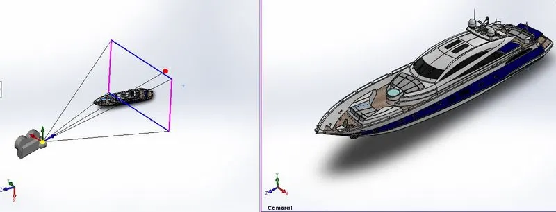
- The whole assembly is then positioned to set the camera view.
- The Appearances and Decals are changed are required.
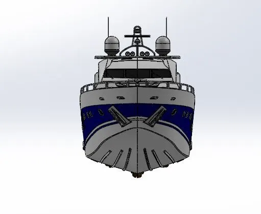
FRONT VIEW:
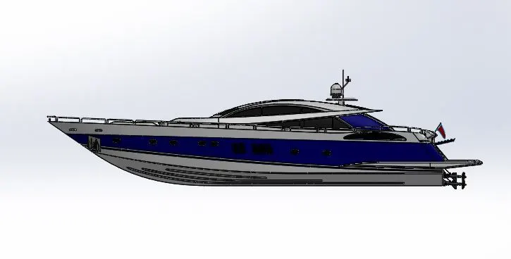
SIDE VIEW:
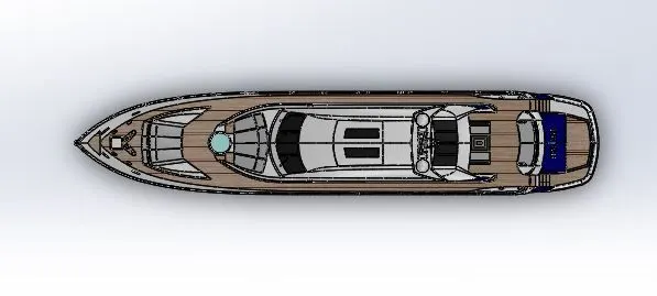
TOP VIEW:
ISOMETRIC VIEW:
CAMERA VIEW:
RENDERED IMAGES:
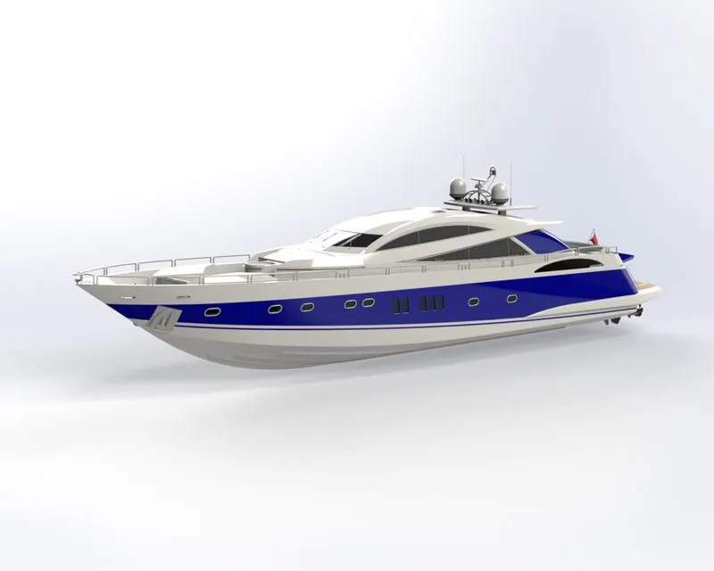
Rendering is the process of creating realistic images of the model in an environment. Renders are obtained using Solidworks Visualise.
RENDERED IMAGE 1:
RENDERED IMAGE 2:
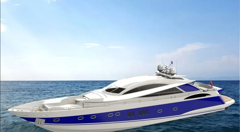
RENDERED IMAGE 3:
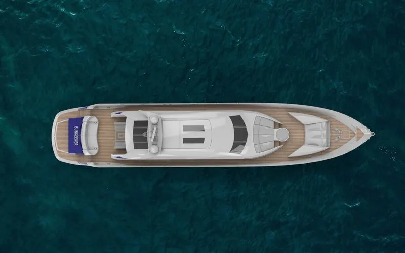
RENDERED IMAGE 4:
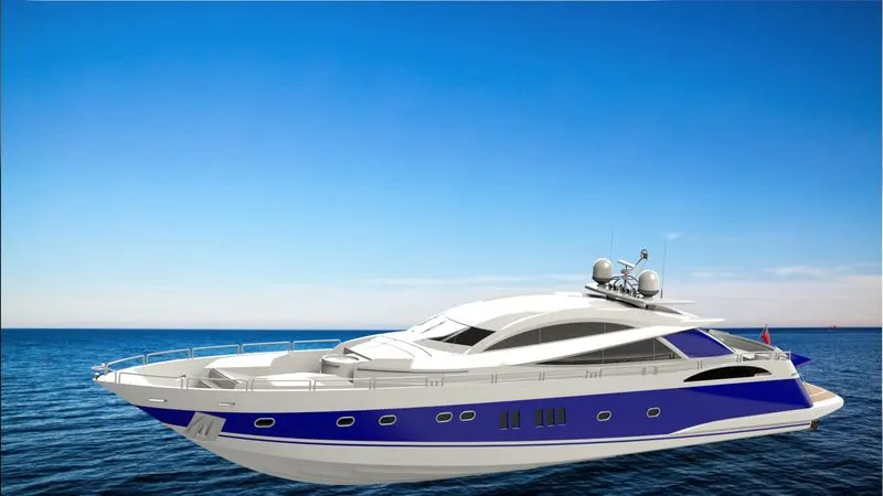
RENDERED IMAGE 5:
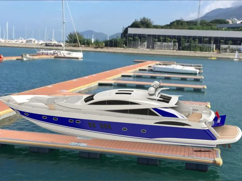
CONCLUSION:
From the modelling and rendering of Sunseeker Predator Yacht using Solidworks, the knowledge to model, assemble and render real time models using Solidworks is obtained. The function of several tools is also known.