Advanced Sheet Metal Design Using NX Cad - Casing Design
ADVANCED SHEET METAL DESIGN OF METAL CASING USING SIEMENS NX CAD
OBJECTIVE:
- To design a sheet metal casing using Siemens NX Cad.
- To create a drafting of the same part in A4 sheet.
INTRODUCTION:
Sheet metal is a metal formed by an industrial process into thin, flat pieces. Sheet metal can be cut and bent into a variety of shapes. Countless everyday objects are fabricated from sheet metal.
NX formerly known as "unigraphics", is an advanced high-end CAD/CAM/CAE software. NX Sheet Metal provides a set of tools within the NX design environment that allows for simple and fast design of sheet metal parts.
DESIGN METHODOLOGY:
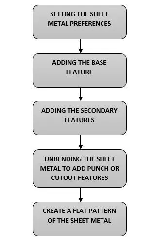
DESCRIPTION:
Tools & their functions:
SKETCH: It is used to create a profile
TAB: It is used to create the base feature of the sheet metal.
FLANGE: It is used to create a extended part of a sheet part.
UNBEND: It is used to unbend the sheet metal by taking any one face as a stationary face.
REBEND: It is used to rebend the sheet metal.
DIMPLE: It is used to lift an area of the model inside a sketch that simulates a stamping tool.
BEAD: It is used to lift material along the contour of a sketch.
FLAT PATTERN: It is used to create a 2D representation of the flattened 3D sheet metal part.
Order of Usage of tools:
- The sheet metal preferences are set as required.
- A required sketch is drawn in the XY plane.
- The base part is created using the TAB command.
- NORMAL CUTOUT feature is used to cut a portion the sheet metal.
- BEND tool is used to bend the sheet metal.
- FLANGES are added to the ends of the bends.
- BREAK CORNER tool is used to create a smooth edge at the sharp corners.
- UNBLEND tool is used to unbend the whole sheet metal.
- After unbending, four SCREW CLEARANCE HOLES are made at the edges of the sheet metal.
- An area of the casing surface is lifted using the DIMPLE tool for the drawn sketch.
- Four BEADS are used to lift the material along the contour of the sketch.
- Finally, the FLAT PATTERN tool is used to create a 2D representation of the flattened 3D sheet metal part
STANDARD VIEWS:
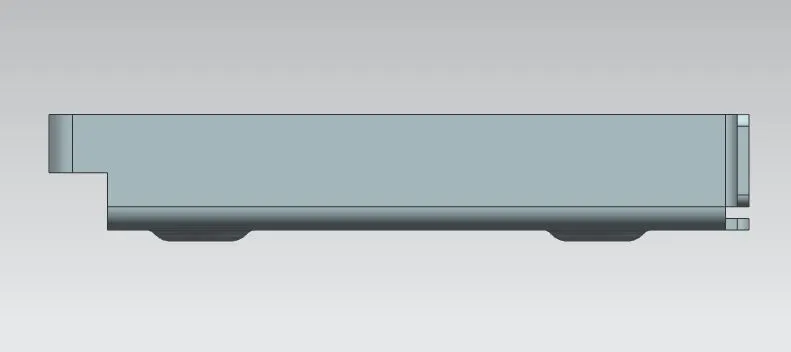
- FRONT VIEW:
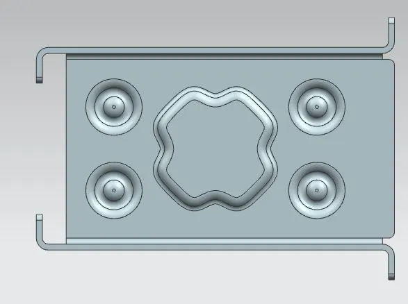
- TOP VIEW:
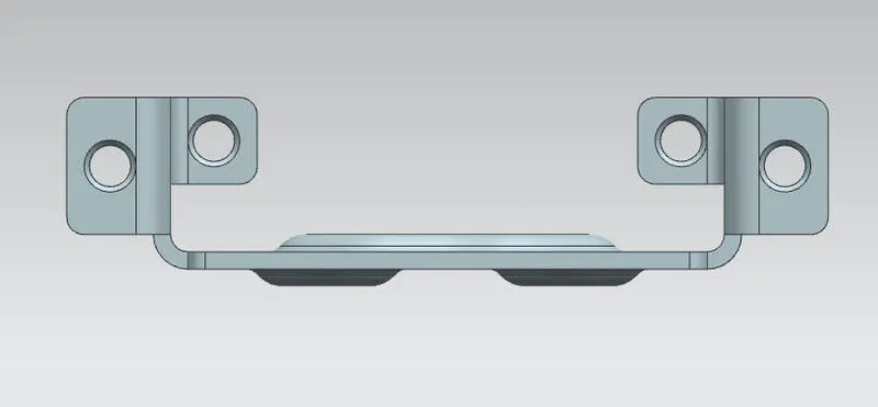
- SIDE VIEW:
- BOTTOM VIEW:

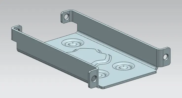
- ISOMETRIC VIEW:
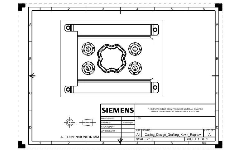
- DRAWING SHEET:
CONCLUSION:
The sheet metal casing is successfully designed using Siemens NX Sheet metal Workbench.