Modeling and Photo Realistic Rendering of American Chopper
MODELLING AND RENDERING OF AMERICAN CHOPPER
OBJECTIVE:
- To model the different parts of an American Chopper using the solid and surface modelling tools.
- To assemble the individually modelled parts of the American Chopper.
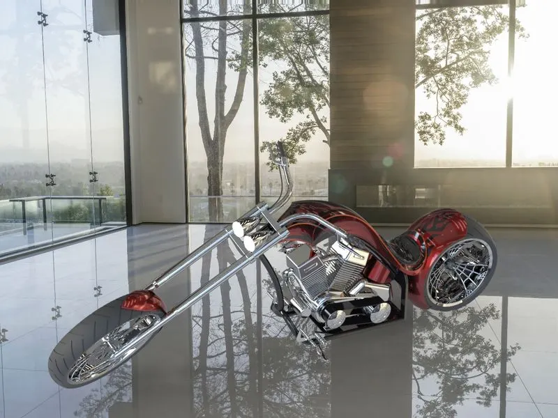
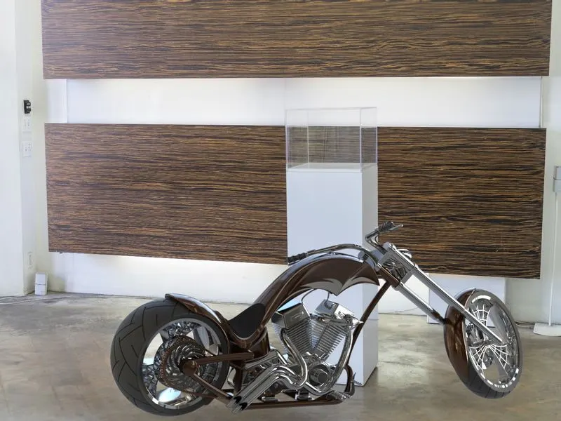
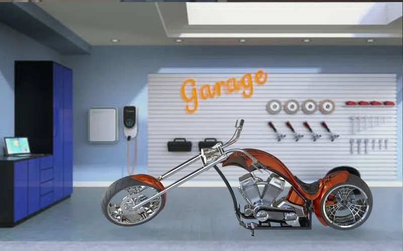
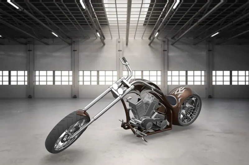
- To use Photoview 360 and Solidworks Visualize to perform a photo realistic rendering of the American Chopper.
INTRODUCTION:
Solidworks is a Computer Aided Design (CAD) and Computer Aided Engineering (CAE) computer program published by Dassault Systemes. It is one of the prominent modelling software available in the market. The parts of the American Chopper are modelled using Solid modelling and Surface modelling tools. All the parts of the American Chopper are then imported to the Assembly workspace and the final assembly of the Chopper is done by adding the required mates. Photoview 360 and Solidworks Visualize are used to obtain the rendered images of the assembled American Chopper.
DESIGN METHODOLOGY:
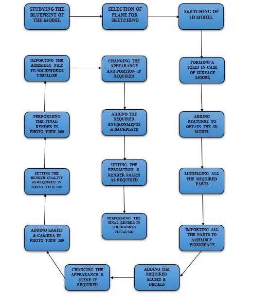
DESCRIPTION:
- TRANSMISSION BELT:
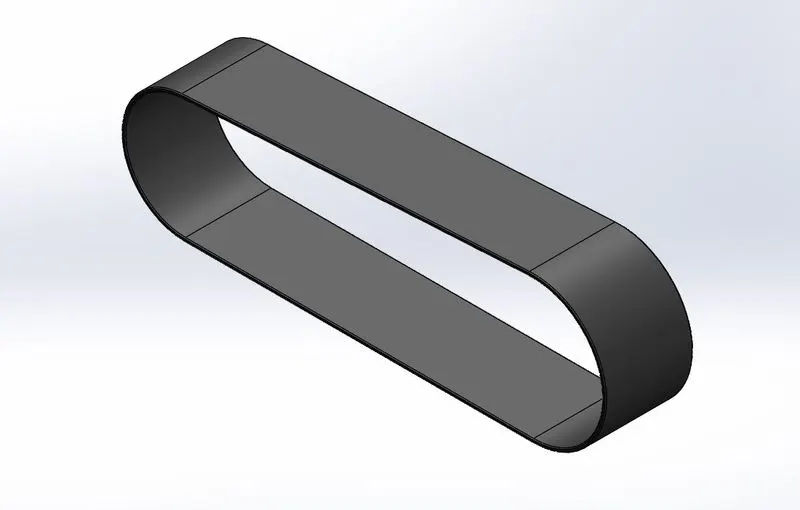
OPERATIONS:
- Sketch the profile as per the required dimensions using Line and Arc
- Constrain the sketch by adding Relations and Smart Dimension.
- Offset the profile.
- Extrude the sketch.
- Provide the required
- Finally, change the Appearance as required.
- KICK STAND:
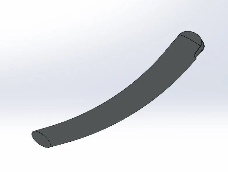
OPERATIONS:
- Draw an
- Use the Spline tool to create a sketch and a plane normal to the end of the spline sketch.
- Draw another ellipse and use Pierce option to join them.
- Use Loft option to connect the 2 Ellipse with the Spline.
- Add a Dome at both the ends.
- Cut- Extrude at one side.
- Use Split command to remove the bottom part at the other side.
- Draw a Circle and Boss- Extrude it at the already Cut- Extruded side to create a pin joint for the kick stand with the chassis.
- Fillets and Appearances are added as required.
- FRONT FENDER:
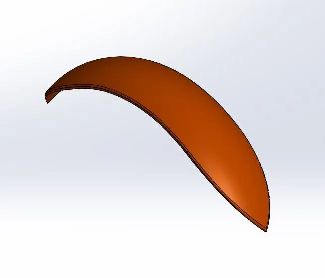
OPERATIONS:
- Draw a 3 Point Arc.
- Offset the arc inside.
- Extend the arc and Power Trim
- Use the Revolve tool to revolve the profile about the axis.
- Dynamic Mirror tool is used to mirror the sketch entities.
- Split tool is used to get the required shape on both the ends of the fender.
- Fillets and Appearances are given as required.
- REAR FENDER:
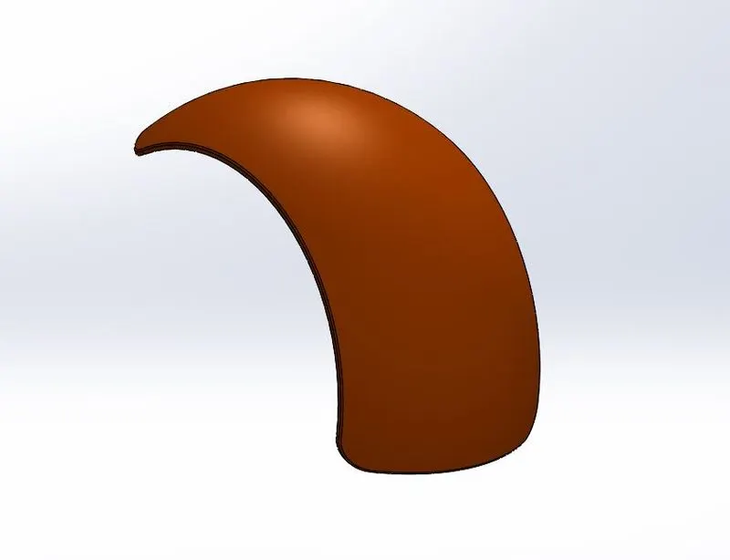
OPERATIONS:
- Draw a 3 Point Arc.
- Offset the arc inside.
- Extend the arc and Power Trim
- Use the Revolve tool to revolve the profile about the axis.
- Dynamic Mirror tool is used to mirror the sketch entities.
- Split tool is used to get the required shape on both the ends of the fender.
- Shell tool is used at the inner side of the fender.
- Fillets are added as required.
- Decals and Appearances are added as desired.
- CHAIN:
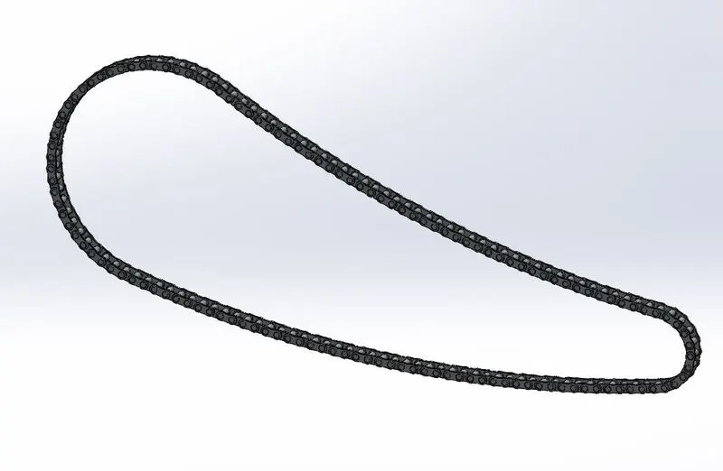
OPERATIONS:
- A curved path is drawn as sketch using Circle, Arc and Power Trim The chain plates and pins will later be formed in this path.
- The required sketch is drawn as per the required dimensions using Ellipse, Circle and Arc
- Chain link 1 and chain link 2 are made as Blocks
- Boss- Extrude is done for the sketch and Fillets are added.
- Curve Driven Pattern tool is used to pattern the pins and chain plates along a predefined curve.
- Wherever the curve become irregular, the pins and chain plates are manually inserted by adding
- Delete/ Keep Bodies option is used to delete the chain plate at the intersection point to provide a proper interference.
- Another chain plate with dimensions that could fit in between the two ends of the chain is sketched and extruded using Boss- Extrude.
- Mirror tool is used to mirror all the chain plates about the axis.
- Add Appearances as required.
- OIL TANK:
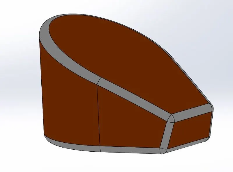
OPERATIONS:
- Draw the sketch as per the required dimensions.
- Extrude the sketch using Boss- Extrude
- Draw another sketch at the mid plane of the previously modelled model.
- Extrude the sketch using Boss- Extrude command similar to the previous one.
- By using Combine option select the common parts between the two models.
- Add Fillets as required.
- Use the Shell tool to create a empty space inside the oil tank.
- Add Appearances and Decals as required.
- PEDAL:
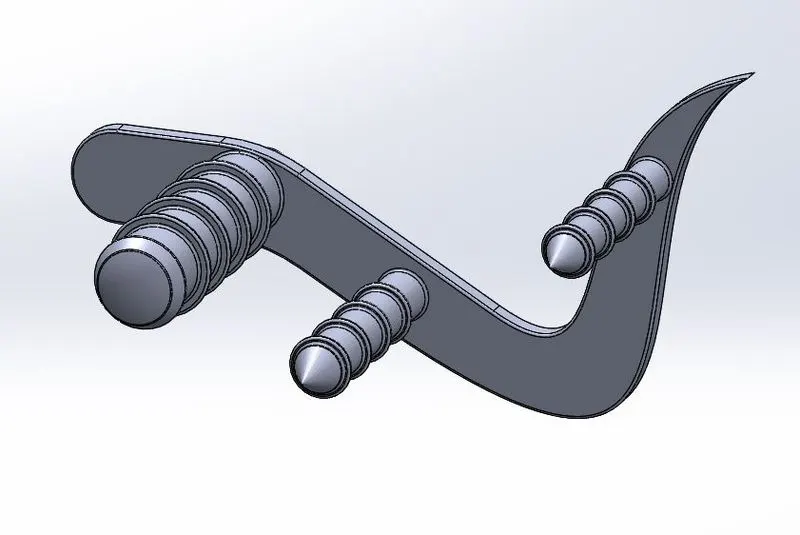
OPERATIONS:
- Draw a sketch as per the required dimensions using Circle, Line, Spline and Arc commands.
- Extrude the sketch using Boss- Extrude
- Draw a sketch and use Revolve tool to revolve the sketch completely to create a model.
- Create a Dome on the revolved part.
- Draw two more sketches and extrude them to form a cylinder.
- Draw a circular sketch around the 3 cylinders and extrude it.
- Add Fillets and Chamfer wherever required.
- Use the Linear Pattern Tool to create similar instances of rings around the cylinders.
- Add Appearances as required.
- FRONT WHEEL:
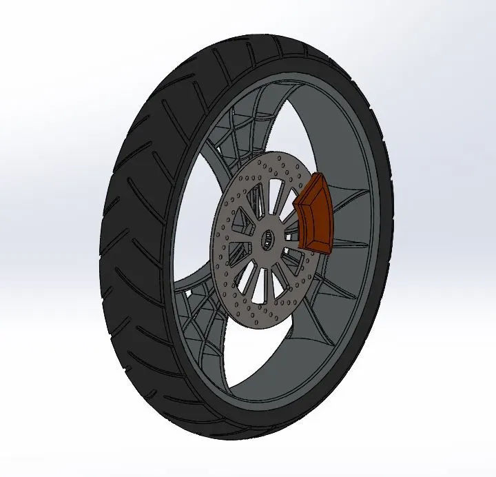
OPERATIONS:
- Draw a sketch using the origin as reference using Line and Arc
- Use the Revolve tool to revolve the sketch about the axis to create the ring for the rim.
- Draw another sketch using Line, Circle and
- Extrude it using Boss- Extrude tool and cut the unnecessary portions using Cut- Extrude to create the rim for the wheel.
- Use Circular Pattern option to create 3 instances of the rim.
- Combine the tyre and rim to make it as a single part.
- Add Fillets wherever required.
- Then, a circular sketch is drawn and extruded at an Offset distance from the centre of rim for the rotor.
- The rotor part is created by modifying the circular part using Cut- Extrude tool and Circular Pattern
- Then, the brake caliper is created by extruding the sketch drawn.
- Chamfer and Fillets are added as required to the brake caliper.
- The tire is created by sketching a profile and revolving it using the Revolve command about the axis same as the rim.
- Threads on the tire are created by using the Cut- Extrude feature and Fillets are added as required.
- Circular Pattern Tool is used to create threads all around the tire.
- Appearances are added as required.
- REAR WHEEL:
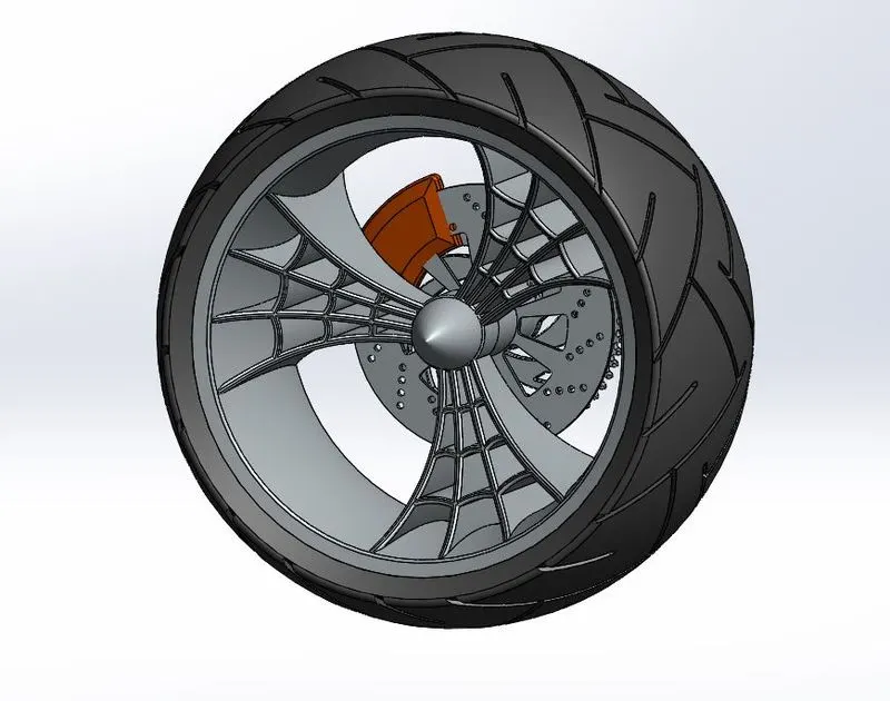
OPERATIONS:
- Draw a sketch using the origin as reference using Line and Arc
- Use the Revolve tool to revolve the sketch about the axis to create the ring for the rim.
- Draw another sketch using Line, Circle and
- Extrude it using Boss- Extrude tool and cut the unnecessary portions using Cut- Extrude to create the rim for the wheel.
- Use Circular Pattern option to create 3 instances of the rim.
- Combine the tyre and rim to make it as a single part.
- Add Fillets wherever required.
- Then, a circular sketch is drawn and extruded at an Offset distance from the centre of rim for the rotor.
- The rotor part is created by modifying the circular part using Cut- Extrude tool and Circular Pattern
- Then, the brake caliper is created by extruding the sketch drawn.
- Chamfer and Fillets are added as required to the brake caliper.
- The tire is created by sketching a profile and revolving it using the Revolve command about the axis same as the rim.
- Threads on the tire are created by using the Cut- Extrude feature and Fillets are added as required.
- Circular Pattern Tool is used to create threads all around the tire.
- Then, a circular sketch is drawn and extruded.
- The sprocket is created by modifying the circular part using Cut- Extrude tool and Circular Pattern
- Appearances are added as required.
- FRONT FORK:
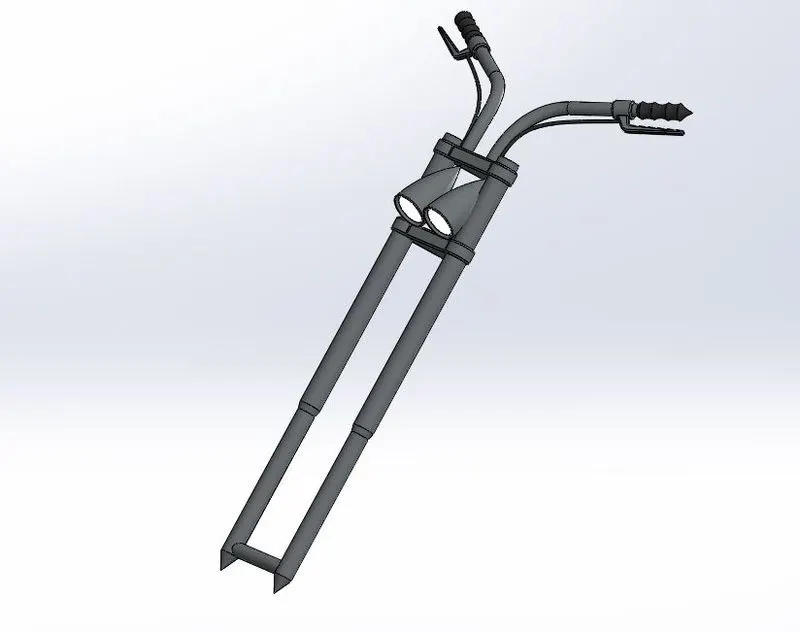
OPERATIONS:
- Draw a sketch using the origin as reference using the Line
- Use the Revolve tool to revolve the sketch about the axis to create the fork.
- Draw another sketch and use the Boss- Extrude feature to extrude the sketch.
- Use Linear Pattern tool to create a pattern of the previously extruded part.
- Draw a sketch and use Revolve tool to create the head lamp.
- Use Cut- Extrude and Dome tool to create a lamp effect in the head lamp part.
- Using Project Curve and Sweep option create the hand bar.
- Use Revolve and Boss Extrude features to create the hand grip and brake.
- Add Fillets wherever necessary.
- Using Project Curve and Sweep option create the brake wire.
- Create a new Reference plane and Mirror the whole part.
- Combine the original with the mirrored part.
- Create a Reference Plane at the bottom of the front fork near the wheel to be used during assembly.
- Add Appearance as required.
- CHASSIS:
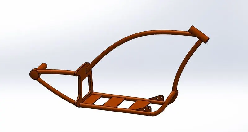
OPERATIONS:
- Import the sketch picture of chopper into the Solidworks work space.
- Draw two Projected Curves and Mirror them about the axis.
- Then, draw a sketch and extrude it using Boss- Extrude and cut a hole using Cut- Extrude.
- Add Fillets as required.
- Create a new Reference Plane and use Sweep tool to develop two hollow tubes.
- Create a Boss- Extrude of a circular profile at the meeting point of the two hollow tubes.
- Create a Dome on the extruded circular profile.
- Create a new Reference Plane and use the Sweep tool to create a hollow tube as per the dimensions required.
- Remove the extra projection of the hollow tube using Split
- Again, create a new Reference Plane and use the Sweep tool to create a hollow tube as per the dimensions required.
- Use the Split tool to remove the internally connected solid surface at the intersection of the two hollow tubes.
- Use the Revolve tool to create another hollow tube which connects the front fork with the chassis.
- Use the Combine tool to join all the parts as a single part.
- Use Boss- Extrude feature to create a rigid support for the chassis at the bottom, clamp for pedal and a clamp for the side stand.
- Add Fillets wherever necessary.
- Add Appearances as desired.
- ENGINE:
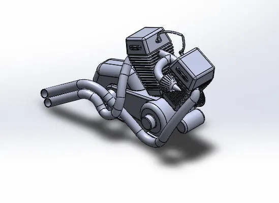
OPERATIONS:
- Import the sketch picture of chopper into the Solidworks work space.
- Draw the required profile using Line and Circle commands and extrude it using Boss- Extrude
- Apply Fillets as required.
- Use the Revolve tool to create a cylindrical structure.
- Create a new Reference Plane and use the Revolve tool to create another cylindrical structure.
- Create splines on the engine for the transmission belt to sit using Boss- Extrude and Circular Pattern
- Use Dome and Cut- Extrude tools to add some more details for the transmission.
- Add Chamfer and Fillets as required to the transmission part.
- Create the engine head in an inclined new Reference Plane using Boss- Extrude, Cut- Extrude, Chamfer, Fillet and Dome
- The engine cooling fins are created by using Linear Pattern
- The engine head is mirrored using the Mirror
- The path for the air intake is created using Sweep
- The base for the engine is created to be fixed in the chassis rigidly using Boss- Extrude
- The sprocket for the chain is created by using Boss- Extrude and Circular Pattern
- The connection between the two engine heads is made by using Sweep tool to create the air intake tube.
- Use the Combine tool to connect the two engine heads, air intake path and transmission as a single part.
- The path to the air filter is created by using Sweep tool in a new Reference Plane.
- The air filter is created by using Revolve, Cut- Extrude and Circular Pattern
- Fillets are again added as required.
- The engine exhaust is made by combining two Project Curves to form a Composite Curve and is modelled using the Sweep tool along the path in a circular profile.
- Similarly, another engine exhaust is made by combining two other Project Curves to form another Composite Curve and is modelled using the Sweep tool along the path in a circular profile.
- The engine exhaust is modified at the open end using split tool.
- The fuel intake tube is modelled using the Sweep
- Appearances are added as required.
- GAS TANK:
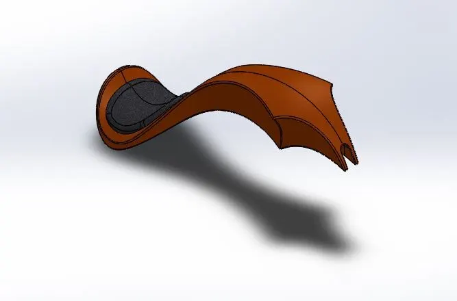
OPERATIONS:
- Import the sketch picture of chopper into the Solidworks work space.
- Create a new Reference Plane and perform a Surface- Sweep and Surface- Trim to create the top profile of the gas tank.
- Create a Project Curve and use the Surface- Loft tool to create the side profile of gas tank.
- Create another Project Curve and use the Boundary- Surface tool to complete the side profile of gas tank.
- Use the Mirror tool to complete the other side profile of the gas tank.
- Use the Surface- Knit tool to combine all the surfaces together.
- Create the seat using Surface- Extrude
- Use the Boundary- Surface and Surface- Loft to enclose the bottom of the gas tank.
- Use the Surface- Knit tool again to combine all the surfaces together.
- Add Fillets as required.
- Use the Cut- Sweep tool to create a cut at the bottom of the gas tank.
- Use the Shell tool to create a hollow cavity inside the gas tank.
- Change Appearances and Decals as required.
- ASSEMBLY:
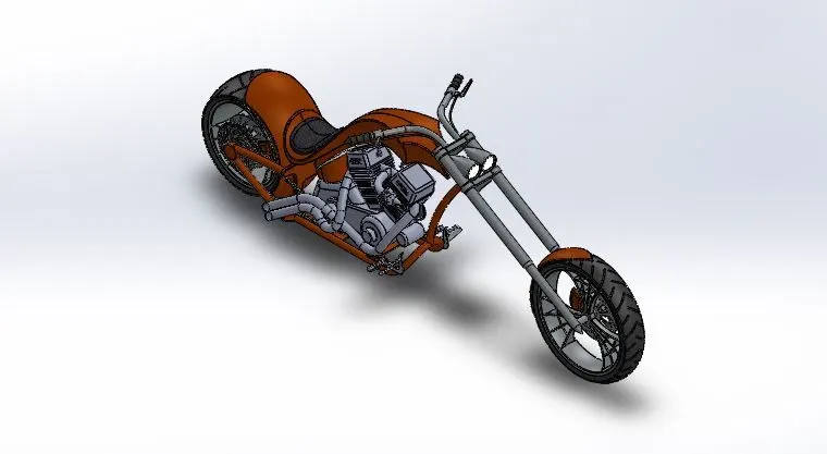
OPERATIONS:
- The chassis part file is first imported into the Solidworks Assembly area and it is then fixed.
- All other parts are imported one after the other. They are then successfully assembled using suitable mates.
- Several mates such as Coincident, Distance, Concentric, Limit Angle, Width, Parallel and Tangent are used to create relation with each part during assembly.
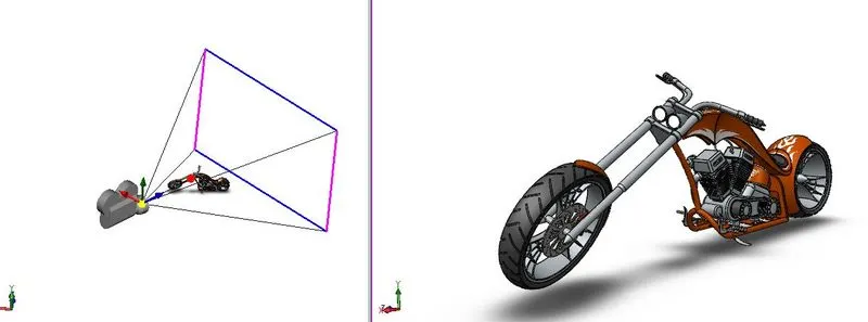
- The whole assembly is then positioned to set the camera view.
- The Appearances and Decals are changed are required.
FRONT VIEW:
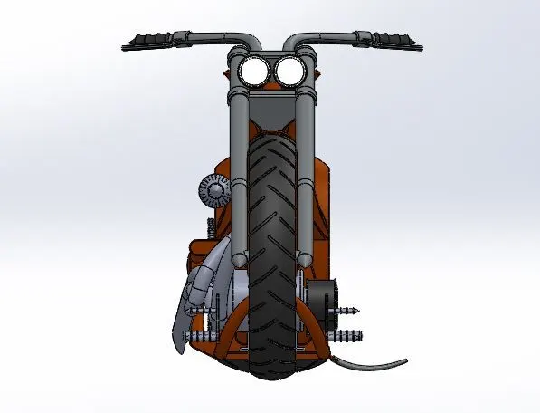
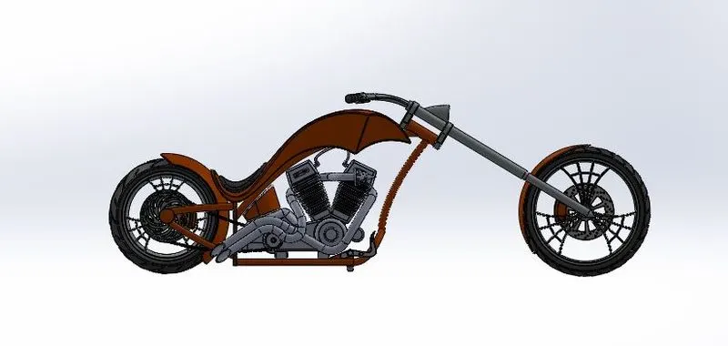
SIDE VIEW:
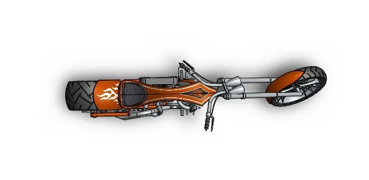
TOP VIEW:
ISOMETRIC VIEW:
CAMERA VIEW:
RENDERED IMAGES:
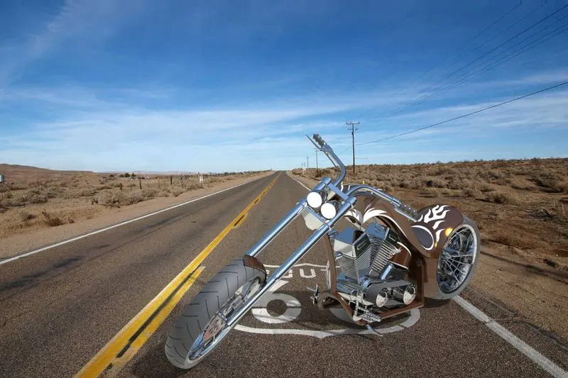
Rendering is the process of creating realistic images of the model in an environment. Renders are obtained using Solidworks Visualise.
RENDERED IMAGE 1:
RENDERED IMAGE 2:
RENDERED IMAGE 3:
RENDERED IMAGE 4:
RENDERED IMAGE 5:
CONCLUSION:
From the modelling and rendering of American Chopper using Solidworks, the knowledge to model, assemble and render real time models using Solidworks is obtained. The function of several tools is also known.