Project - Speed Control of a Direct Current (DC) motor
Aim:
To build a Simulink model for speed control of direct current (DC) motor.
Objective:
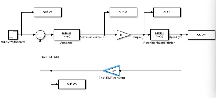
- In this project, a Simulink model for the DC motor will be first developed per the schematic shown in Figure 1.
- Use the Proportional, Integral, and Derivative (PID) control design knowledge gained in the training to design, develop and test a controller to maintain a desired speed for the motor.
Solution:
In this project, a Simulink model for the DC motor will be first developed per the schematic.
ω(s) / Vs(s) =Kt/J La s2 + (J Ra + B La) s+(B Ra + kt km)
Dc motor parameter:
% this file contains the design parameters to model dc motor
J = 0.01 ; % moment of inertia kg-m^2
B = 0.1;   % motor viscous constant N-m-s
km = 0.01; % Back emf constant v/rad/s
kt = 0.01; % motor torque constant N-m/amp
Ra = 1 ; % resistance of armature circuit ohm
La = 0.5 ; % inductance of armature circuit in henries
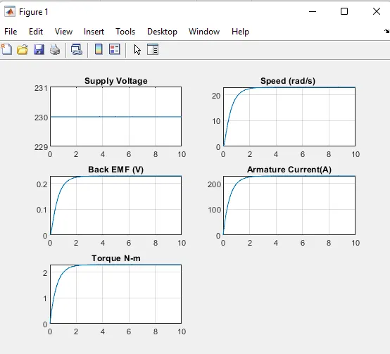
Dc motor plot:
figure(1)
subplot(321);plot(out.time,out.vs);grid;title('Supply Voltage');
subplot(322);plot(out.time,out.w);grid;title('Speed (rad/s) ');
subplot(323);plot(out.time,out.vb);grid;title('Back EMF (V)');
subplot(324);plot(out.time,out.ia);grid;title('Armature Current(A)');
subplot(325);plot(out.time,out.t);grid;title('Torque N-m');
Plot:
PID Design for Speed control of DC motor:
%Parameter for speed control of dc motor PID
J = 0.01 ; % moment of inertia kg-m^2
B = 0.1;   % motor viscous constant N-m-s
km = 0.01; % Back emf constant v/rad/s
kt = 0.01; % motor torque constant N-m/amp
Ra = 1 ; % resistance of armature circuit ohm
La = 0.5 ; % inductance of armature circuit in henrys
%PID design from DC_motor_PID_design.m
%Load the parameters of DC motor
run Dc_motor_PID_parameter.m;

%PD design
A = [-B/J kt/J; -km/La -Ra/La];
B = [0; 1/La];
%pole placement design
f = 1;
wn = 2*pi*f;
zeta = 0.5;
p1 = -zeta*wn + wn*sqrt(zeta^2-1);
p2 = -zeta*wn - wn*sqrt(zeta^2-1);
P = [p1;p2];
k = place(A,B,P);
Kp = k(1);
kd = k(2);
kp = 38.3133;
kd = -2.85;
ki = 10;
figure(4)
subplot(321);plot(out.time,out.vs);grid;title('Supply Voltage');
subplot(322);plot(out.time,out.w);grid;title('Speed (rad/s) ');
subplot(323);plot(out.time,out.vb);grid;title('Back EMF (V)');
subplot(324);plot(out.time,out.ia);grid;title('Armature Current(A)');
subplot(325);plot(out.time,out.t);grid;title('Torque N-m');
subplot(326);plot(out.time,out.u);grid;title('control -u');
Simulink model:
Out put:
Control Design Objectives:
Settling time < 2s
Overshoot < 5%
Steady state error < 1%
Initially assuming Ki=10
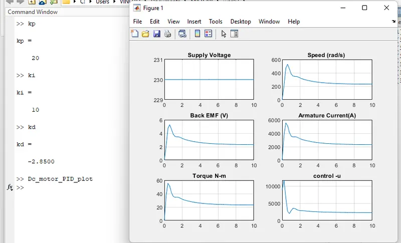
To reduce the overshoot, the Kd value is increased to -0.9:
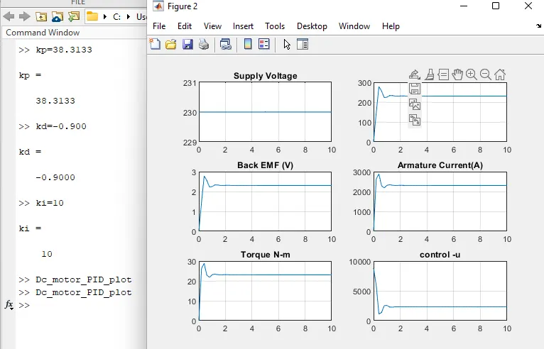
To reduce the overshoot further, the Kp value is decreased:
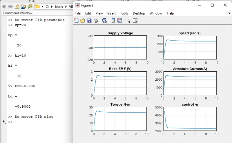
On further decreasing the Ki value to 3, the desired characteristic is obtained.
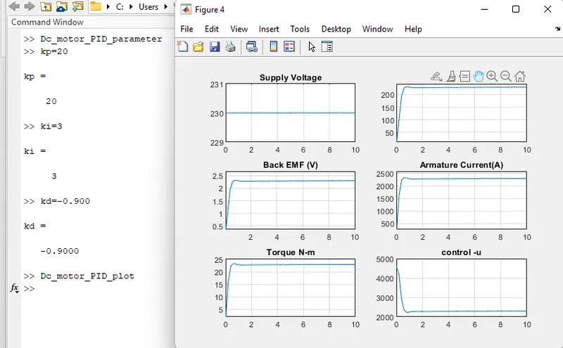
We can observe that the settling time <2s, Overshoot<5% and Steady state error <1%
Result:
The Simulink model for the DC motor design created Using the Proportional, Integral, and Derivative (PID) control design knowledge gained in the training to designed, developed and tested a controller to maintain a desired speed for the motor.
- Mohammed Mannanwhich coefficients were use in rotor inertia and friction block