Project - Speed Control of a Direct Current (DC) motor
Aim - This Project we make the with help mathematical eqution and make the DC Motor and Try to Maintain Desired Speed for the during the running condition with help of PID
Working -
Using Kirchoffs Voltage one Can
Vs= Ra*ia + La*dia/dt + Vb
Back Emf angular Velocity and Torque
Vb= Km d*theta/dt
Here Km and Kt are The Back Emf and Torque Contant
Design Parametre For the DC motor For the Motor Controlled
J -Moment Of Intertia Constant 0.01 kgm^2
B- Motor Viscous Fricition Constant - 0.1 Nms
Km- Back EMF Constant - 0.01 v/radins/s
KT-Motor torque Constant - 0.01 Nm/Ampere
Ra- Armature Resitance -1 ohm
La -Armature inductance- 0.5 H
With help of this parameter we make mathmatical equation of Motor
Now we have to Find Out the Kp and Ki and Kd for the Controlled the Motor speed
for we used the State Space Module
d/dt*[theta;i]=[-B/J KT/J; -km/La -Ra/La]*[theta ; i] + [0;1/La]*Vs
A=[-10 1; 0.02 2] B=[0 ; 2]
Now we used Pole placemnt
Fn= 1.0 ; Frequncy
wn= 2*pi*Fn Natural Frquncy
zeta=0.9 Underdamped Condition
p1= -zeta*wn+wn*sqrt(zeta^2-1)
p2=-zeta*wn-wn*sqrt(zeta^2-1)
P=[p1;p2];
K=Place(A,B,P)
Kp=13.2005
Kd=1.6549
Ki=1
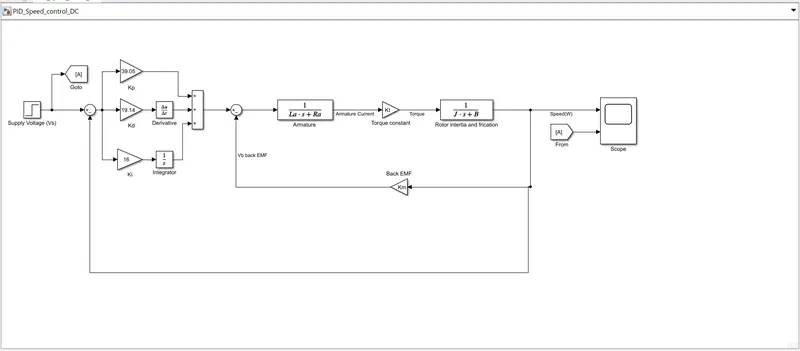
Now Design the Model Of DC Motor and PID controller in Simulink
For Better Tracking Performace we Take
Kp=39.43
Kd=19.14
Ki=16
we take Input Supply As Step Function
then we take Three gain block for Ki ,Kd,Kp for the Kd we take derivative block and For the Ki we take the integrator block
then we take the tranfer function block for the dc motor parameter armature and Rotor Intertia and Frication
we calacualte the speed
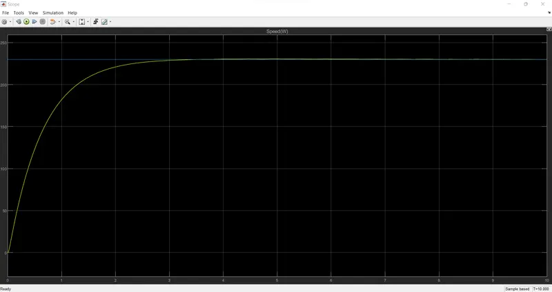
Output Plot for the Tracking Performace of the Vechicle speed according to the desired speed and actule speed
Conclusion-
we try to maintain the speed of motor according to ref speed with help of PID Controller we get better tracking perfromace with find out the best Ki,Kp ,Kd for controlled speed