Project 3
Aim- Bascially This Project Developed For In EV we used Auxiliary Load For This Load we Need Converter So we We developed DC-DC Buck Converter it Step-Down The Voltage Provide supply to the Auxiliary Load (Radio, horn, accessories, etc..)
Given Data-
Vin=48 v
Vout= 12 v
Output Current= 10 A
inductor current ripple is less than 30% of the average inductor current
output voltage ripple of the capacitor is less than 5%.
Step1-Draw a circuit Schematic diagram of the buck converter
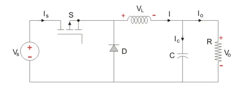
In This Circuit we used Input Voltage ,One Power Switch (MOSFET,IGBT) ,Inductor Coli,Capacitor,Diode,Resitance load
In this Circuit working In two Mode This Circuit Will Work Switch On Mode and Switch OFF
Mode One- Switch ON ,Diode OFF
Circuit Below
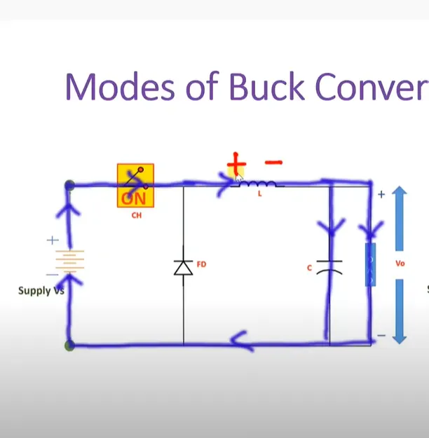
Working Of This Circuit a
When we start supply Switch is ON Then supply goes to the Inductor then inductor coil energies with politrites + to - and then goes to the resitance Load the back to supply voltage and circuit complete and also capacitor aslo charged in this circuit Diode stop to flow current due to anode side is - and cathod side is + its works like reversed Bised
Mode 2- Switch OFF and Diode ON
Circuit Below
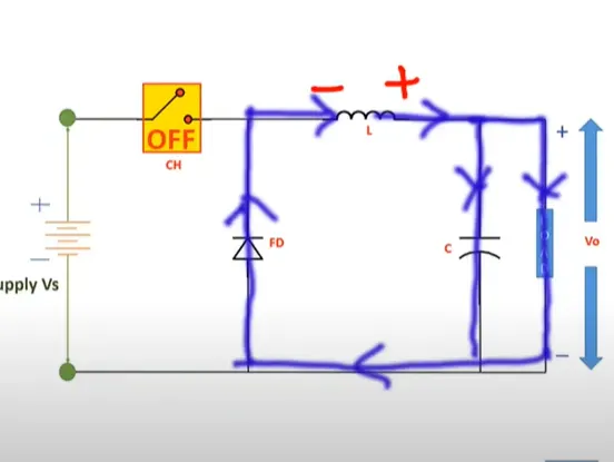
Working Of this Circuit
When we switch is off then Supply stop and when switch is on that time our inductor coil is charged now switch is off that inductor start discharging but changes the politrity of inductor coil and just bechuse of diode gets anode side geta + and cathode side we get - so diode aslo start conducting supply inductor coil through then resitance load and capacitor and diode trough complete the circuit like this circuit work
Calacultion Part-
VL (on) * Ton+VL (off) *Toff=0
(Vs-Vo)*Dt+(-vo)*(1-D)*T=0
Vo=Dvs
D=Vo/Vs
D=12/48= 0.25
0.25 Ducty Cycle
Vout =Iout *R Fs=50khz
R=Vout/Iout
R=12/10=1.2 Ohm
Then let us design for 30% ripple in the inductor
Delta IL =30/100*10 =3 A
Find The Inductor
L=Vout (1 -D)/Fs *Delta *IL
L= 12*(1-0.25)/50*3=0.06 mH
let us design the output Capacitor
C=1-d/8*L*Fs*(Delta Vo/Vo)
C= 0.75/ 8*0.06*50^2*0.05
C=0.0125
C=12.5 mF
Now We get the values
L= 0.06 mH
C= 12.5 mF
R=1.2 Ohm
D=25%
Now Simulate the Circuit in Simulation
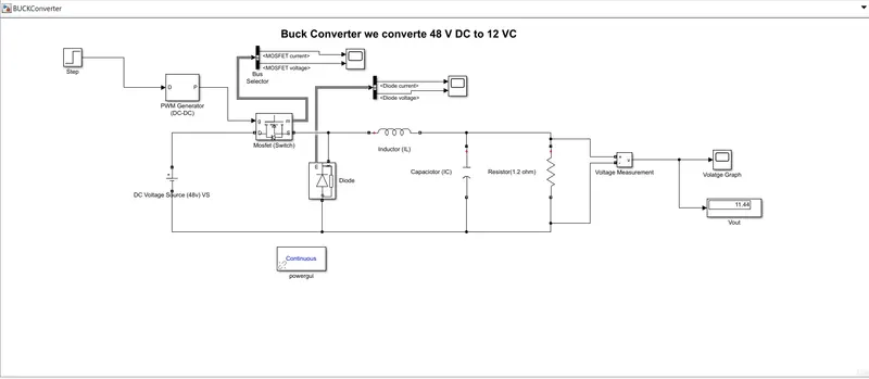
Now Design the Circuit with help of DC Voltage Supply connect with MOSFET Switch For Controlling The Volatge For Switch we used PWM Genertor To genrtae the PWM so we Controlled the Voltage we used Indcutor coil in series and Capcitor across the Resiatnce Load and Diode and with help of Voltage measurment we used for the Mesure the Voltage
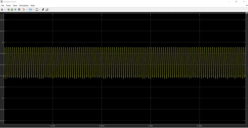
Output Voltage Graph-
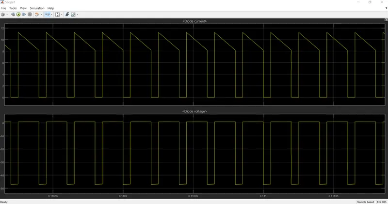
Diode Voltage and Current Graph
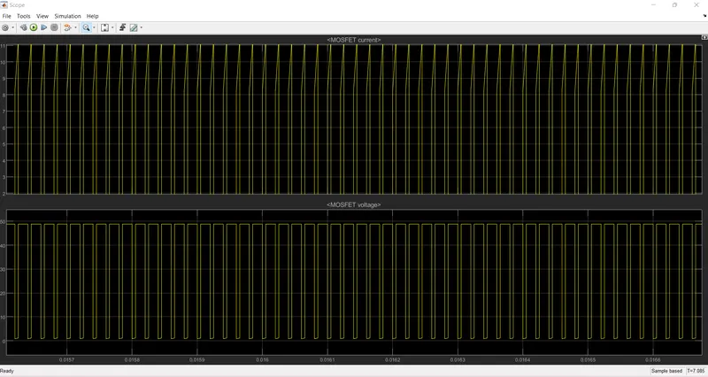
MOSFET Voltage and Current Graph
Peak Current OF Diode Is 10.1 A
Peak Current Of MOSFET is 11.1 A
Peak Voltage OF Diode Is 0.7 V
Peak Voltage Of MOSFET is 49.3 V
Conclusion = With The Of Buck Converter we Step Down The Input Voltage and Given to Voltage to the Auxiliary Load smothly we can say this is the DC-DC converter