Project - Speed Control of a Direct Current (DC) motor
- Dc machine can function as both generator and motor.
- It has rotor with an armature winding providimg the electrical circuit
- It has a stator part w ith a field winding serving as magnet when energised
- While operating as generator a prime mover is connected with rotor allowing it to rotate in the magnetic fieled created by field winding this cause emf in the conductor mounted on the rotor and contributes to voltage generation.
- While operating as motor electrical energy supllied to the armature and field winding contributes to rotating magnetic field that forces the rotor to rotate which generate a mechanical torque
- There are two inputs that contributes the voltage generation one is the speed of the router and the other is a field excitation.
Vs = Ra Ia + La dia / dt +Vb
Vb =Km dQ/dt where dq= angular velocity
torque = Kti
Km & Kt are back emf & torque constant
PID design for speed control of DC motor
J = moment of inertia rotor
B = motor viscous friction constant
Km = back EMF constant
KT = motor torque constant
R= armature resistance
L =armature inductance
for desiginig apid controller
J=0.01;% momemt of inertia of rotor
B=0.1; % motor viscousfriction constant
km=0.01; %back emf constant
kt=0.01; % motor torque constant
Ra=1.0; % armature resistance
La=0.5; % armature indutance
vs= 150; % suplly voltage
A =[-B/J kt/J; -km/La -Ra/La]; % Matrices A & C
C= [0 ; 1/La];
%pole placement Design
f=1.0;
wn=2*pi*f;
zeta=0.98; %underdamped system
p1=-zeta*wn+wn*sqrt(zeta^2-1);
p2=-zeta*wn-wn*sqrt(zeta^2-1);
p=[p1;p2];
K=place(A,C,p);
kp=8.1540;
kd=0.1575;
ki=0.0;
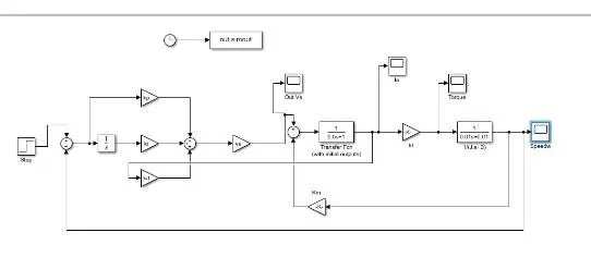
Here I have used step block as a reference And followed by gain Kp, ki & kd . Kp equal to 8.1 5 Kd equal to 0.15 and Ki are equal to zero
.followed by a voltage source with 150V . then it is given to a transfer function .
graphical representation of torque ,speed, armature current & voltage is obtained