Project - Speed Control of a Direct Current (DC) motor
P I D Controller for DC motor:
- THEORY:
In DC motor armature is rotates due to magnetic induction.
we supply the current in armature winding and hence in circuit at another side of armature there is field winding which generates a magnetic field around armature winding
which create a condition of generating torque
and changing in flux provides back emf in circuit first equation is as
Ldi/dt+Ri = v - Kb*d(theta)/dt
where d(theta)/dt is w (angular velocity)
we connected a load to rotor
which has moment of inertia of rotor and some parameters are
J = Momentum of inertia of rotor
B =Dmaping constant
R = Armature resistance
L = Armature inductance
Kb = Back EMF
Kt = Motor torque constant
V = voltage
motor torque T = Kt*I
and Vb = Kb*w= Kb*d(theta)/dt
as per newton's law
J*d^2(theta)/dt^2 + B*d(theta)/dt = Kt*I
in laplacian domain
I(s) = [V(s)-sKb*tht(s)]/(Ls+R)
and w(s) = s*tht(s) = Kt*I(s)/(Js+B)
from both equation we would get open loop transder function
for angular velocity and angle displacepent
G(s) = w(s)/v(s) = Kt/[(Ls+R)(Js+R)+Kt*Kb]
and for
G'(s) = tht(s)/v(s) = Kt/s*[(Ls+R)(Js+R)+Kt*Kb]
AIM:
our task to develop a controller which control the angular velocity of DC motor system
and controller is PID controller
proportional derivative and integral controller
there are basically three constant Kp, Kd and Ki
Kp helps in reach out to desire value quickly but let overshoot increase
Kd basically decrese the fluctuation in error
and Ki remove the all errors inregrated till present point
we have define several terms like moment of inetia , friction coefficient and many more
j = 0.01; % moment of intertia
B = 0.1; %friction
kb = 0.01; %back emf const
kt = 0.01 %torque const
ra = 1; %resistance
la = 0.5 %inductance
and our x matrix is [w;i] where w and i is angular speed and current respectively
furthermore A and B matrix are
a = [-B/j kt/j; -kb/la -ra/la];
b = [0 ;1/la];
fn = 10; %frequency
wn = 2*fn*pi;
zeta = 0.9;
p1 = -zeta*wn+wn*sqrt(zeta^2-1);
p2 = -zeta*wn-wn*sqrt(zeta^2-1);
p = [p1;p2];
k = place(a,b,p);
from here we would get k1 and k2 values as kp and kd from k matrix
those value are kp = 1458.4 kd = 50.5
and we will decide ki value manually
the model are as follow:
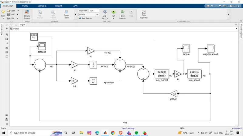
this model consist of system of dc motor with PID controller
we will see the result for various input angular velocity
let's start with step input
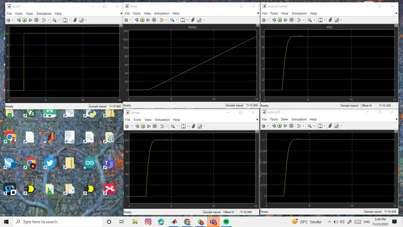
.
.
.
lets do for ramp input
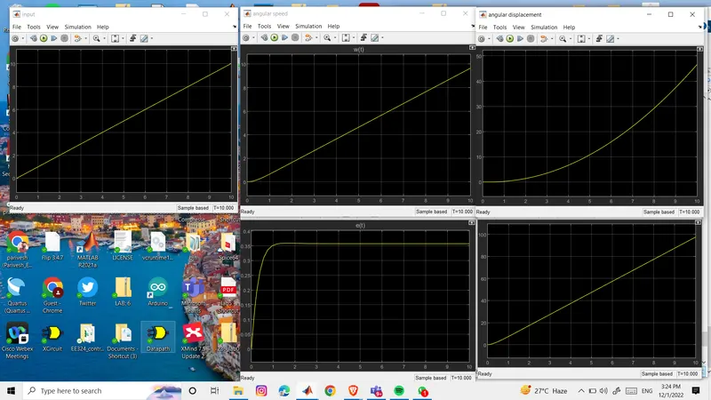
now for square wave
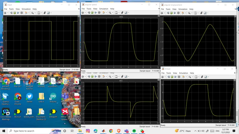
now for sine wave
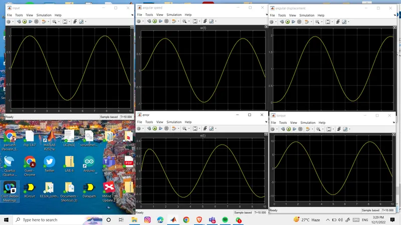
we can see there is delay in following the input