Project - Speed Control of a Direct Current (DC) motor
In this project, a Simulink model for the DC motor will be first developed per the schematic shown in Figure 1.
Use the Proportional, Integral, and Derivative (PID) control design knowledge gained in the training to design, develop and test a controller to maintain a desired speed for the motor.
- Matlab script to define modeling and control design parameters
%Design parameter of Dc motor
J=0.01; % moment of inertia
B1=0.1; %motor viscosity
Km=0.01;%Back emf
Kt=0.01; %motor torque
Ra=1.0; % armature resistance
La=1.0; % industance
%equivalent parameter
wn=6.2832; %rad/ sec sqrt(k/m)
fn=1; %hz wn/2*pi;
% design parameter
zeta=1.01;
Ki=100;
%desired poles
p1=-zeta*wn+wn*sqrt(zeta^2-1);
p2=-zeta*wn-wn*sqrt(zeta^2-1);
P=[p1;p2];
% A&B matrices
A=[-B1/J Kt/J;-Km/La -Ra/La];
B=[0;1/La];
%pole placement design
K=place(A,B,P);
%kp and kd are obtain
Kp=K(1);
Kd=K(2);
- Simulink model to simulate and verify the design:
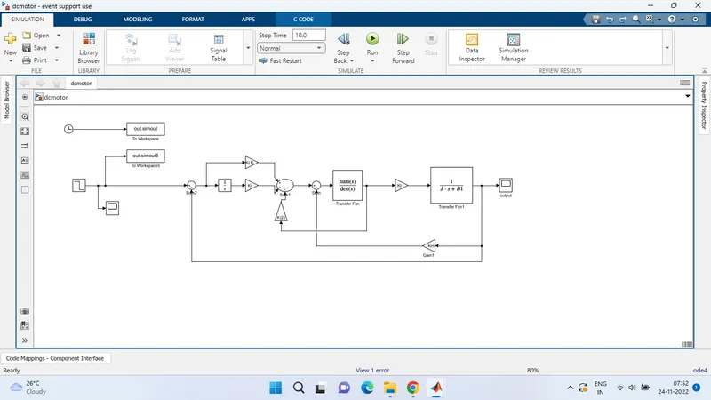
OUTPUT:
i have given my step input as 5 and and initial value as 5 and final value as 5
and ki value as 0 kp and kd value i have derived from pole placement function for zeta value .7
And my output looks as shown below
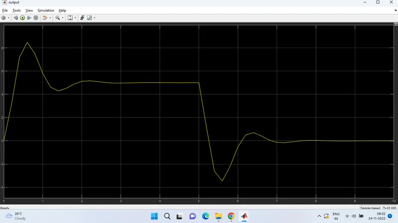
My system has taken 2.5 sec to achive its speed control
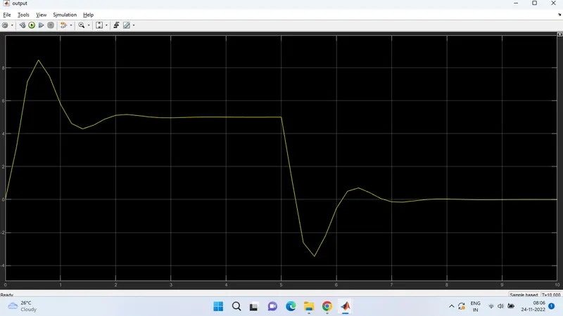
and by futher increasing my Ki value to 1000
My output As shown below :
And futher i have changed the value of Kp and Kd by changing the zeta value as 1.01 and Ki value as 100
And my output as shown below :
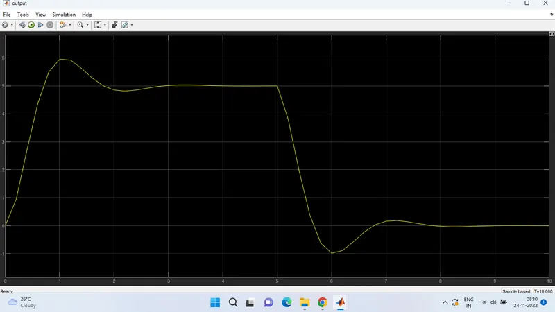
And i have tested my system with various value of step input and my system works fine .