Project - Speed Control of a Direct Current (DC) motor
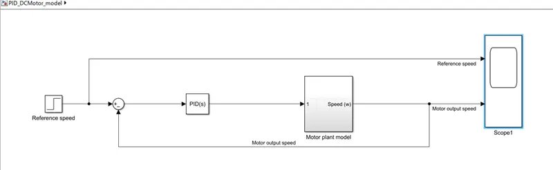
Aim: In this project, a Simulink model for the DC motor will be first developed per the schematic shown in Figure 1.
Use the Proportional, Integral, and Derivative (PID) control design knowledge gained in the training to design, develop and test a controller to maintain a desired speed for the motor.
- The blocks used to develop the model is as shown:
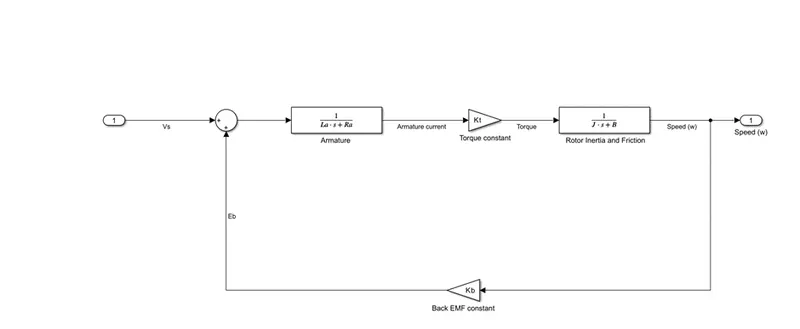
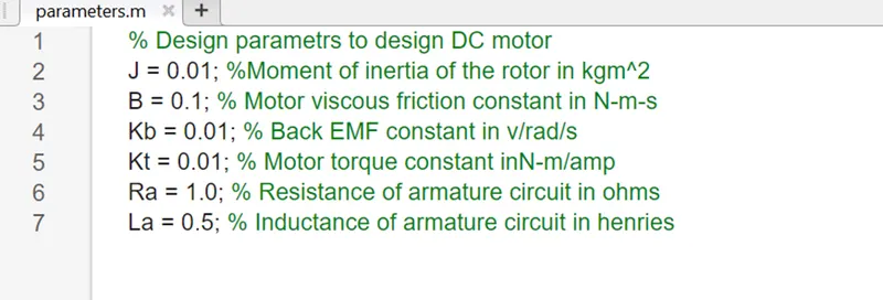
- The input parameters used to simulate the above model is as follows:
In this project the PID controller is placed in the forward path, so that its output becomes the voltage applied to the motor’s armature. The feedback signal is a velocity, measured by a tachometer. The output velocity signal is y(t) is summed with a reference or command signal R(t) to form the error signal e(t). Finally, the error signal is input to the PID controller. The PID controller is defined by the following relationship between the controller input e(t) and the controller output u(t) that is applied to the motor armature.
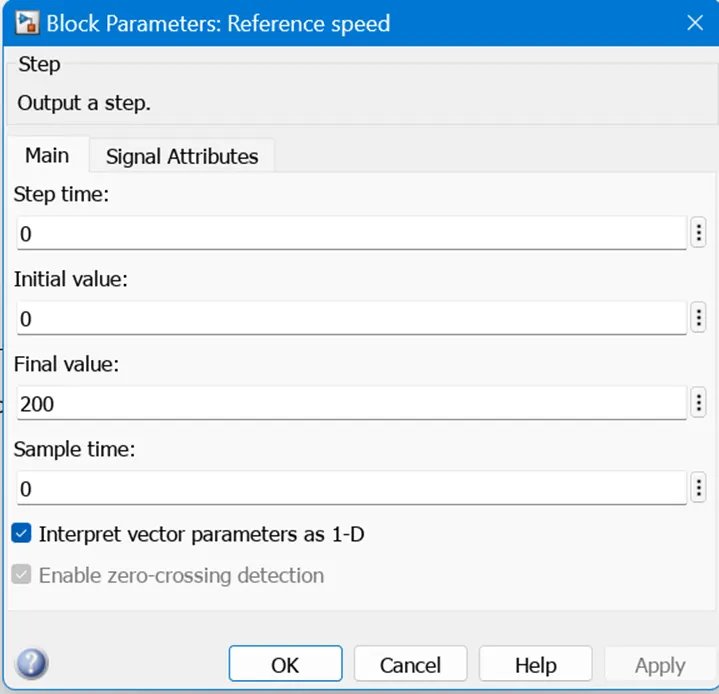
Reference speed:
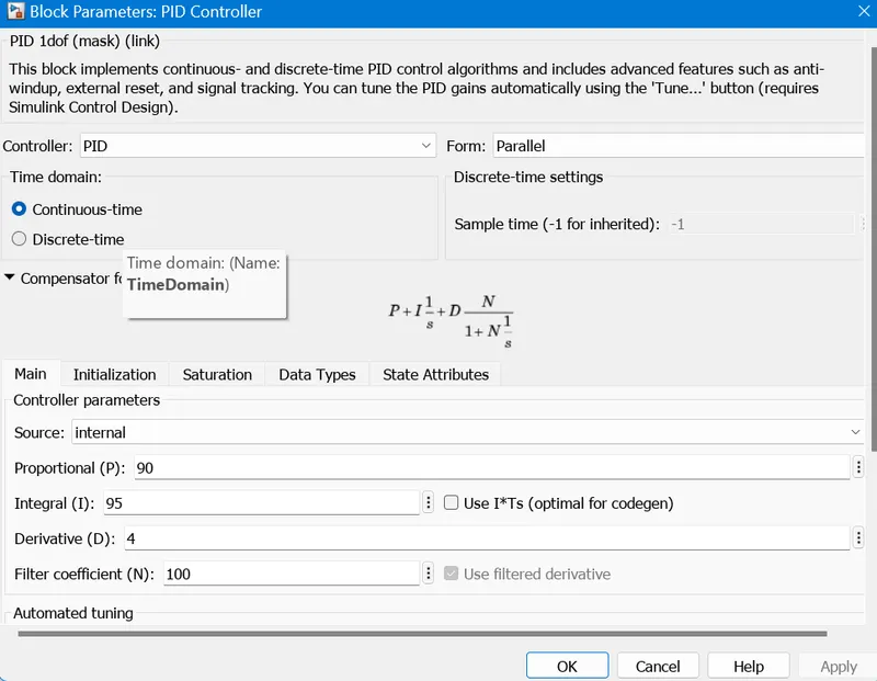
The output for the PID controller P = 90 I = 95 D =4 is:
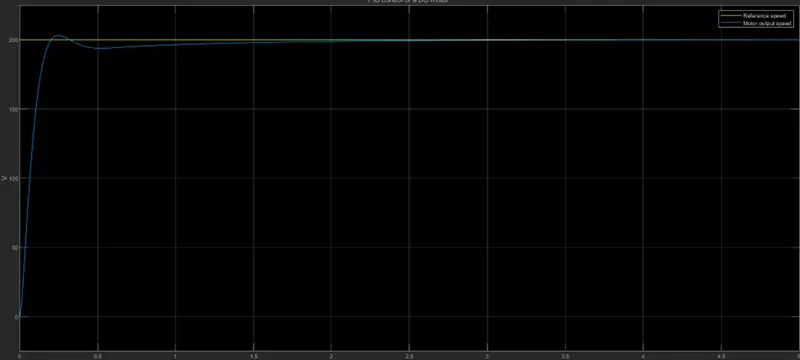
From the output we can see that there is an overshoot that is less than 10% and in less that 1 second it settles down and follows the input speed given i.e., 200