Project - Speed Control of a Direct Current (DC) motor
AIM:
a Simulink model for the DC motor will be first developed per the schematic .Use the Proportional, Integral, and Derivative (PID) control design knowledge gained in the training to design, develop and test a controller to maintain a desired speed for the motor.
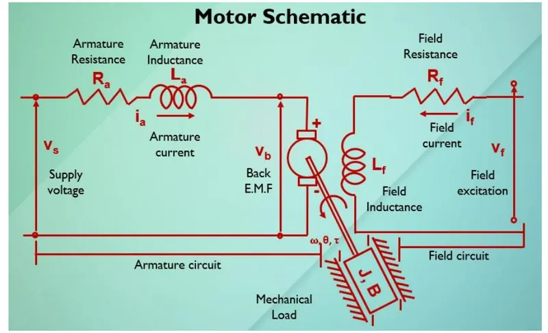
J= Moment of Inertia of Rotor
B= Damping Constant
R= Armature resistance
L= Armature inductance
Vb = Back emf constant
KT = Motor Torque constant
V= Voltage
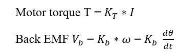
MATLAB PARAMETERS:
USED BLOCKS:
- clock
- to workspace
- step block
- sum block
- integrator block
- gain block
- transfer function
- scope
EXPLANATION:
A proportional–integral–derivative controller (PID controller or three-term controller) is a control loop mechanism employing feedback that is widely used in industrial control systems and a variety of other applications requiring continuously modulated control. The proportional integral derivative controller produces an output, which is the combination of the outputs of proportional, integral, and derivative controllers. The feedback from the plant whichever is a controllable parameter is given as input to the PID controller and the processed error is minimized to get the desired output if tuning of the parameter is done optimally. The mathematically PID controller can be defined by the following equation where e(t) is the error signal with respect to time, KP, KI and KD are PID constants.
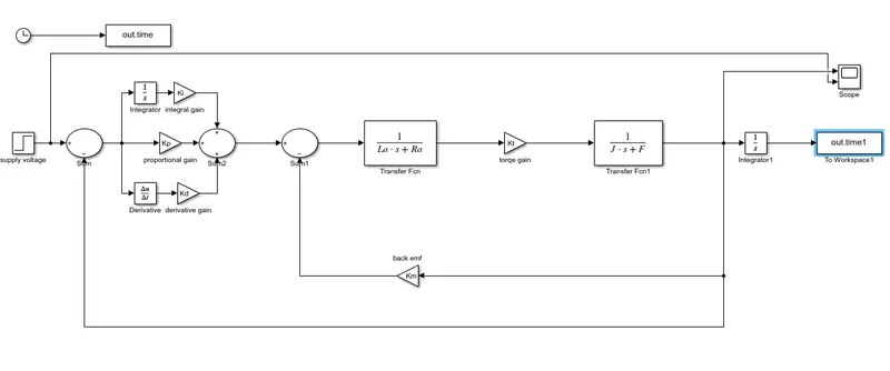
- The project is based on speed control of a DC Motor by using PID Controller
- initally, simulink model of a DC Motor is contructed,then make it as system called"DC MOTOR".
- Then subsystem DC motor is conected to the discrete PID controller to maintain the desired speed as it is.
- After that PID controller begin with Kkp,kd,ki as 38.3133,-2.8584,100 after tuning accordingly,we can respectively. to obtain control design objectives
SIMULINK MODEL:
SIMULINK MODEL OF DC MOTOR
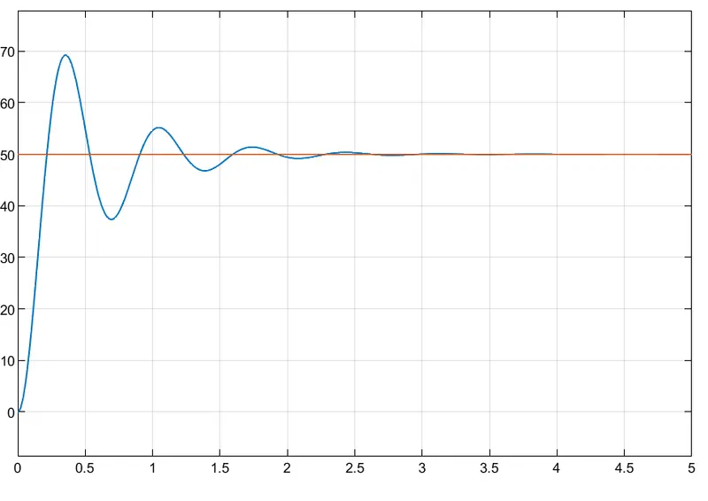
RESULT:
TO maintain a desired speed for the motor (speed=50)
To maintain a desired speed for the motor(speed=230)
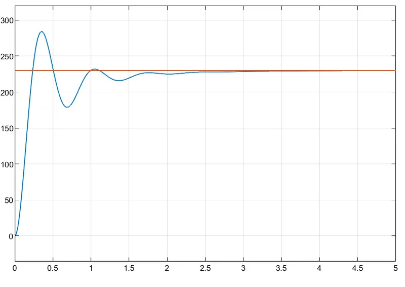
- speed is the controllable parameter, so we will set the reference speed in step block .
- Subtract the actual speed from the reference speed to generate the error signal e(t)
- Add Kp as K(1) and Kd as K(2) parameter determined from place command (K=place(A,B,P)). (use gain block to mention values of Kp, Kd, and Ki)
- The feedback for Kd is provided from the output current of the model .
- Add Ki manually with gain and integrator block and tune different values of Ki and check the impact of it on results.
CONCLUSION:
we have designed in this project a simulink model for the DC motor as shown in picter and also we use the proportional integral and derivative PIDcontrol design knowledge gained in the traing to design develop and test a controller to maintain a desired speed for the motor.