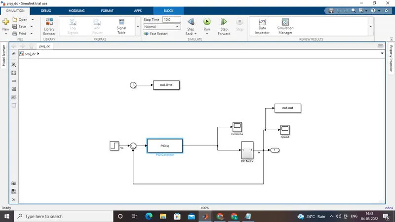
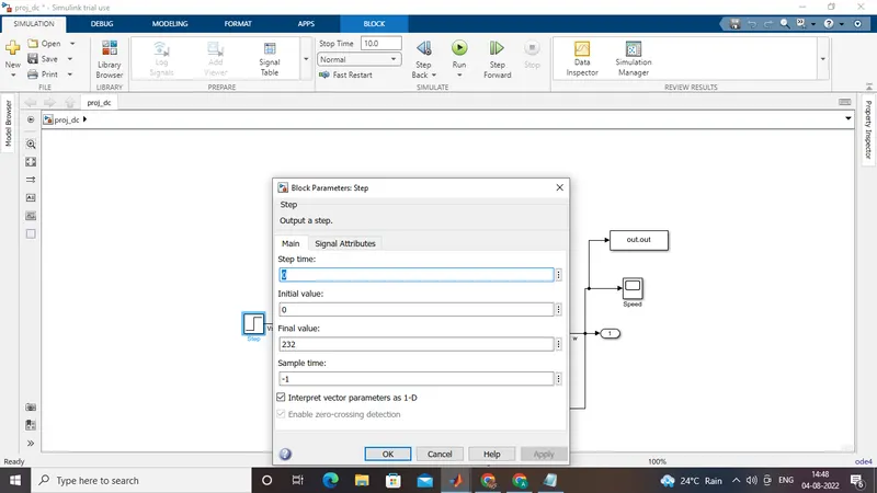
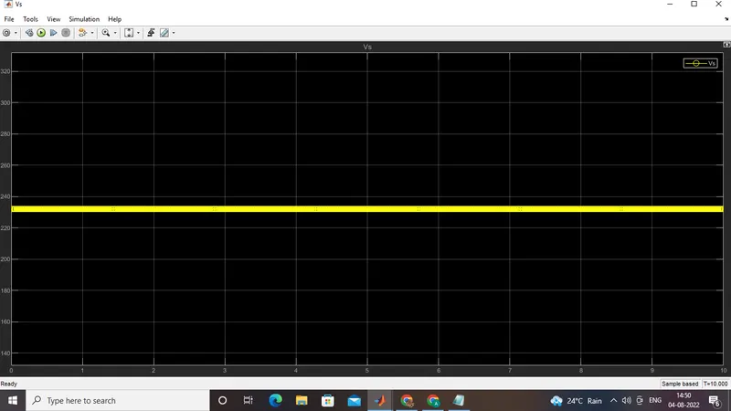
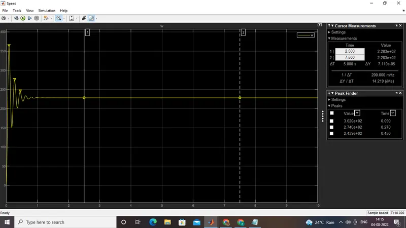
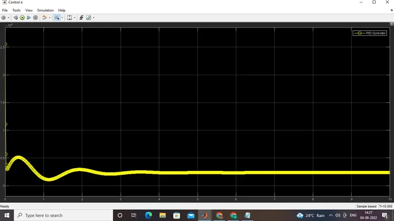
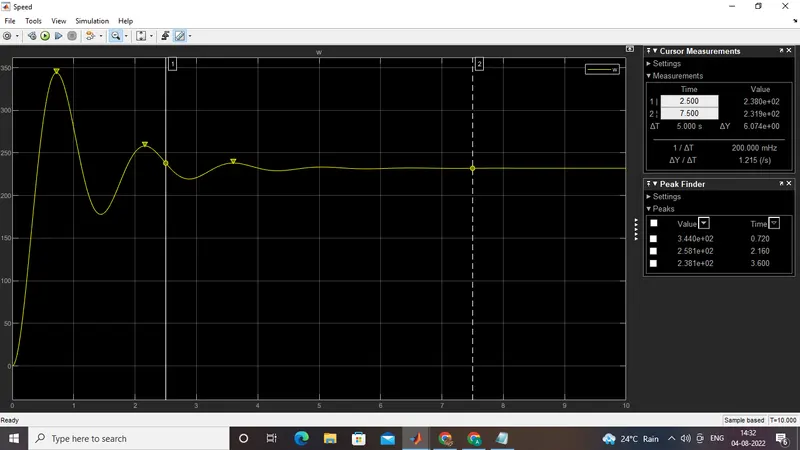
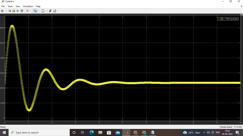
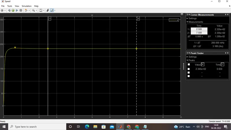
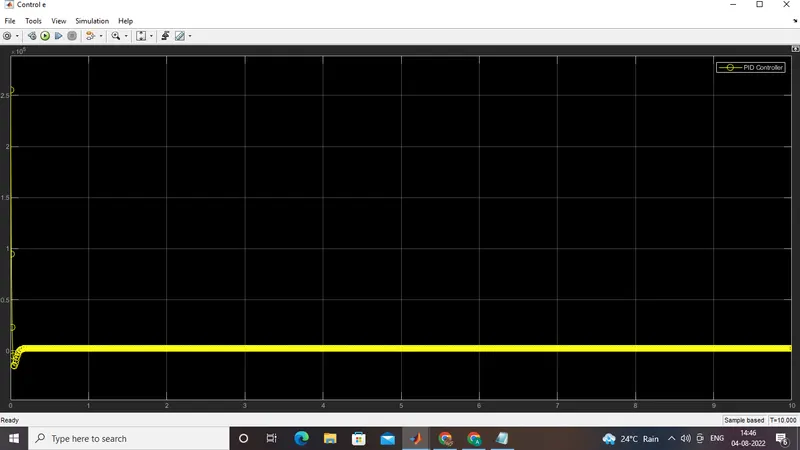
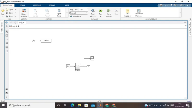
The DC motor is analysed using Kirchoff's law and Newtons law. The following are the equations representing the DC motor Vs is the supply voltage. Vb is the back emf, Ia armature current, T torque, all other parameters are defined below. The block diagram is simulated using simulink blocks and the speed is obtained for Vs=230v.
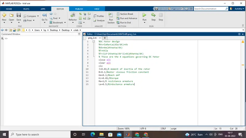
%DC Motor design
%Vs=IaRa+La(dIa/dt)+Vb
%Vb=Km(dtheeta/dt)
%T=KtIa
%T=J(d^2thetta/dt^2)+B(dthetta/dt)
% These are the 4 equations governing DC Motor
close all
clear all
clc
J=0.01;% moment of inertia of the rotor
B=0.1;%motor viscous friction constant
Km=0.1;%back emf
Kz=0.01;%torque
Ra=1;% resistance armature
La=0.5;%inductance armature
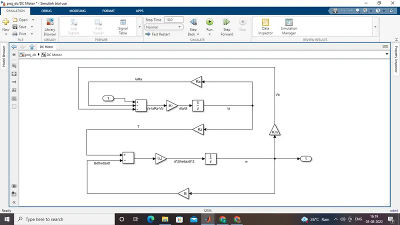
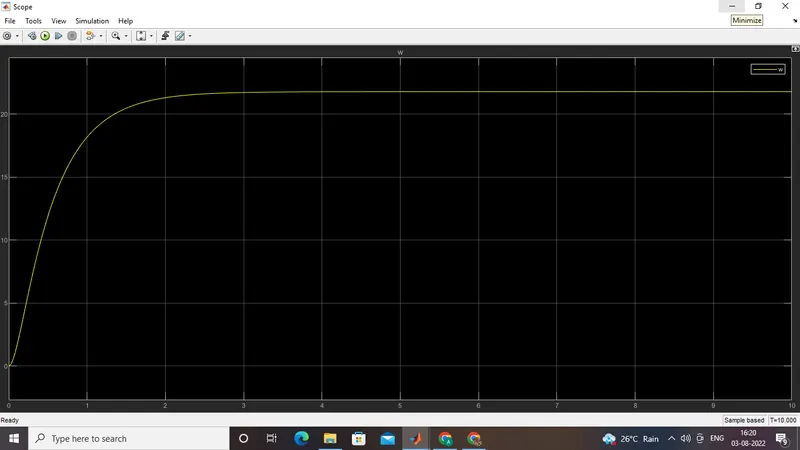
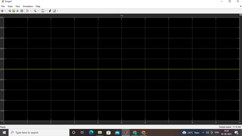
Uncontrolled speed
Input V
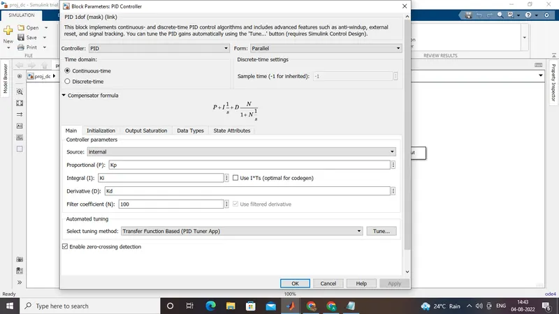
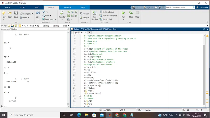
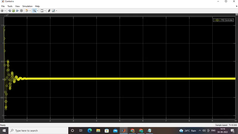
Now controller is designed using PID. The zeta value is initially choosen to be 0.5. The pole placement is done using place command. The program is shown below:
%DC Motor design
%Vs=IaRa+La(dIa/dt)+Vb
%Vb=Km(dtheeta/dt)
%T=KtIa
%T=J(d^2thetta/dt^2)+B(dthetta/dt)
% These are the 4 equations governing DC Motor
% close all
% clear all
% clc
J=0.01;% moment of inertia of the rotor
B=0.1;%motor viscous friction constant
Km=0.1;%back emf
Kz=0.01;%torque
Ra=1;% resistance armature
La=0.5;%inductance armature
%design of PID controller
zeta = 0.5;
fn=1;
wn=2*pi*fn;
m=100;
k=wn^2*m;
p1=-zeta*wn+wn*sqrt(zeta^2-1);
p2=-zeta*wn-wn*sqrt(zeta^2-1);
A=[0 1;-k/m 0];
B1=[0;1/m];
p=[p1;p2]
z=acker(A,B1,p)
% Kd=10
% Kp=100
Kd=z(1)
Kp=z(2)
Ki=0;
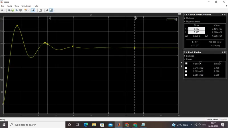
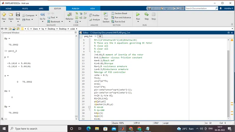
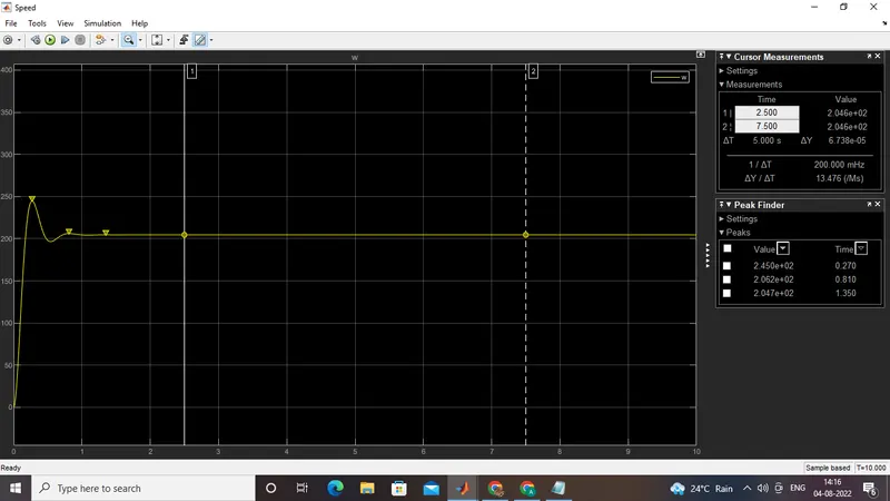
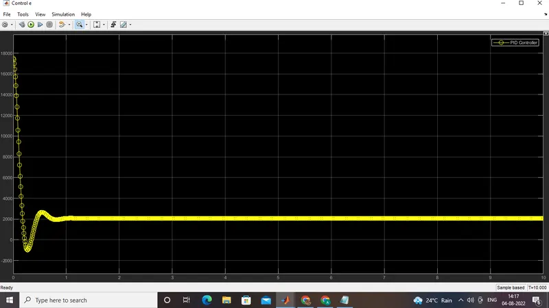
The values of zeta, m is modified and the results are shown below:
%DC Motor design
%Vs=IaRa+La(dIa/dt)+Vb
%Vb=Km(dtheeta/dt)
%T=KtIa
%T=J(d^2thetta/dt^2)+B(dthetta/dt)
% These are the 4 equations governing DC Motor
% close all
% clear all
% clc
J=0.01;% moment of inertia of the rotor
B=0.1;%motor viscous friction constant
Km=0.1;%back emf
Kz=0.01;%torque
Ra=1;% resistance armature
La=0.5;%inductance armature
%design of PID controller
zeta = 0.5;
fn=1;
wn=2*pi*fn;
m=12;
k=wn^2*m;
p1=-zeta*wn+wn*sqrt(zeta^2-1);
p2=-zeta*wn-wn*sqrt(zeta^2-1);
A=[0 1;-k/m 0];
B1=[0;1/m];
p=[p1;p2]
z=acker(A,B1,p)
% Kd=10
% Kp=100
Kd=z(1)
Kp=z(2)
Ki=0;
%DC Motor design
%Vs=IaRa+La(dIa/dt)+Vb
%Vb=Km(dtheeta/dt)
%T=KtIa
%T=J(d^2thetta/dt^2)+B(dthetta/dt)
% These are the 4 equations governing DC Motor
% close all
% clear all
% clc
J=0.01;% moment of inertia of the rotor
B=0.1;%motor viscous friction constant
Km=0.1;%back emf
Kz=0.01;%torque
Ra=1;% resistance armature
La=0.5;%inductance armature
%design of PID controller
zeta = 0.5;
fn=1;
wn=2*pi*fn;
m=12;
k=wn^2*m;
p1=-zeta*wn+wn*sqrt(zeta^2-1);
p2=-zeta*wn-wn*sqrt(zeta^2-1);
A=[0 1;-k/m 0];
B1=[0;1/m];
p=[p1;p2]
z=acker(A,B1,p)
% Kd=10
% Kp=100
% Kd=z(1)
% Kp=z(2)
% Ki=0;
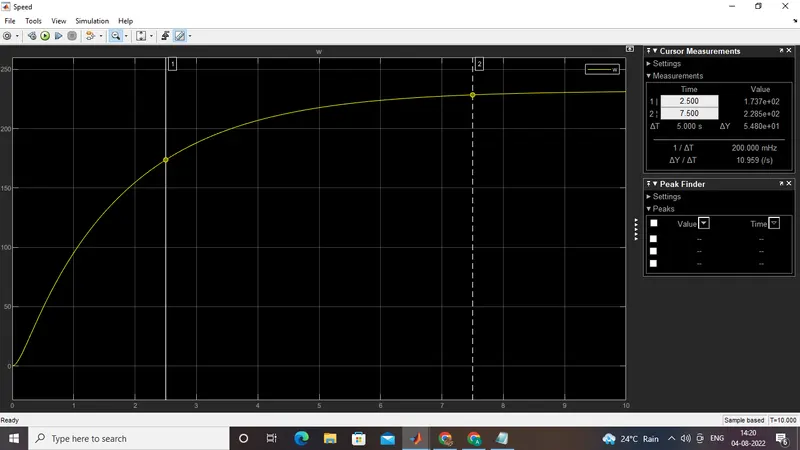
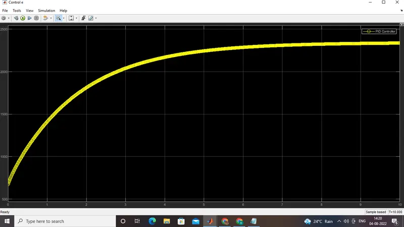
Kp= 2.9
Ki= 5.5
Kd= 0.0001
zeta =1
Kp= 10
Ki= 100
Kd= 100
%DC Motor design
%Vs=IaRa+La(dIa/dt)+Vb
%Vb=Km(dtheeta/dt)
%T=KtIa
%T=J(d^2thetta/dt^2)+B(dthetta/dt)
% These are the 4 equations governing DC Motor
% close all
% clear all
% clc
J=0.01;% moment of inertia of the rotor
B=0.1;%motor viscous friction constant
Km=0.1;%back emf
Kz=0.01;%torque
Ra=1;% resistance armature
La=0.5;%inductance armature
%design of PID controller
zeta = 1;
fn=1;
wn=2*pi*fn;
m=12;
k=wn^2*m;
p1=-zeta*wn+wn*sqrt(zeta^2-1);
p2=-zeta*wn-wn*sqrt(zeta^2-1);
A=[0 1;-k/m 0];
B1=[0;1/m];
p=[p1;p2]
z=acker(A,B1,p)
% Kd=10
% Kp=100
% Kd=z(1)
% Kp=z(2)
% Ki=0;
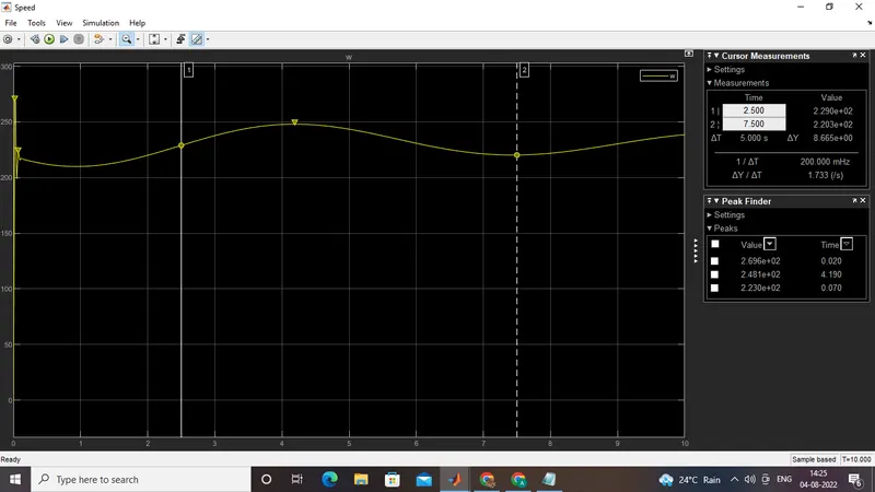
Kp= 10
Ki= 100
Kd= 100

%DC Motor design
%Vs=IaRa+La(dIa/dt)+Vb
%Vb=Km(dtheeta/dt)
%T=KtIa
%T=J(d^2thetta/dt^2)+B(dthetta/dt)
% These are the 4 equations governing DC Motor
% close all
% clear all
% clc
J=0.01;% moment of inertia of the rotor
B=0.1;%motor viscous friction constant
Km=0.1;%back emf
Kz=0.01;%torque
Ra=1;% resistance armature
La=0.5;%inductance armature
%design of PID controller
zeta = 1;
fn=1;
wn=2*pi*fn;
m=12;
k=wn^2*m;
p1=-zeta*wn+wn*sqrt(zeta^2-1);
p2=-zeta*wn-wn*sqrt(zeta^2-1);
A=[0 1;-k/m 0];
B1=[0;1/m];
p=[p1;p2]
z=acker(A,B1,p)
% Kd=10
% Kp=100
% Kd=z(1)
% Kp=z(2)
% Ki=0;
Kp= 10
Ki= 100
Kd= 1
%DC Motor design
%Vs=IaRa+La(dIa/dt)+Vb
%Vb=Km(dtheeta/dt)
%T=KtIa
%T=J(d^2thetta/dt^2)+B(dthetta/dt)
% These are the 4 equations governing DC Motor
% close all
% clear all
% clc
J=0.01;% moment of inertia of the rotor
B=0.1;%motor viscous friction constant
Km=0.1;%back emf
Kz=0.01;%torque
Ra=1;% resistance armature
La=0.5;%inductance armature
%design of PID controller
zeta = 1;
fn=1;
wn=2*pi*fn;
m=12;
k=wn^2*m;
p1=-zeta*wn+wn*sqrt(zeta^2-1);
p2=-zeta*wn-wn*sqrt(zeta^2-1);
A=[0 1;-k/m 0];
B1=[0;1/m];
p=[p1;p2]
z=acker(A,B1,p)
% Kd=10
% Kp=100
% Kd=z(1)
% Kp=z(2)
% Ki=0;
Kp= 10
Ki= 100
Kd= 0
The best design is obtained for
%DC Motor design
%Vs=IaRa+La(dIa/dt)+Vb
%Vb=Km(dtheeta/dt)
%T=KtIa
%T=J(d^2thetta/dt^2)+B(dthetta/dt)
% These are the 4 equations governing DC Motor
% close all
% clear all
% clc
J=0.01;% moment of inertia of the rotor
B=0.1;%motor viscous friction constant
Km=0.1;%back emf
Kz=0.01;%torque
Ra=1;% resistance armature
La=0.5;%inductance armature
%design of PID controller
zeta = 1;
fn=1;
wn=2*pi*fn;
m=12;
k=wn^2*m;
p1=-zeta*wn+wn*sqrt(zeta^2-1);
p2=-zeta*wn-wn*sqrt(zeta^2-1);
A=[0 1;-k/m 0];
B1=[0;1/m];
p=[p1;p2]
z=acker(A,B1,p)
% Kd=10
% Kp=100
% Kd=z(1)
% Kp=z(2)
% Ki=0;
Kp= 100
Ki= 200
Kd= 10