Project 2 Adaptive Cruise Control
Aim of the Project
The main aim of this project is to develop a adaptive cruise control feature for passenger cars. Based on the distance of the vehicle in front, the speed of the car gets adjusted automatically. The objectives are:
- Developing Adaptive Cruise Control feature as per the Requirement Document using MATLAB Simulink.
- Follow all the MBD related processes: Requirement Tagging & Traceability, SLDD creation, Configuration Parameter changes, Model Advisor check & Code Generation.
- In Configuration Parameters: enable “Support Floating Numbers” under Code Generation settings.
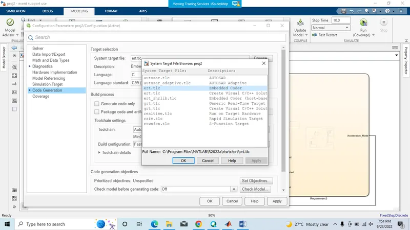
- Use Embedded Coder to generate the code.
- If choosing code generation, Storage class for Input signals: ImportedExtern; Storage class for Output signal: Export to File; Storage class for local signals: localizable; Storage class for calibration signals: Const.
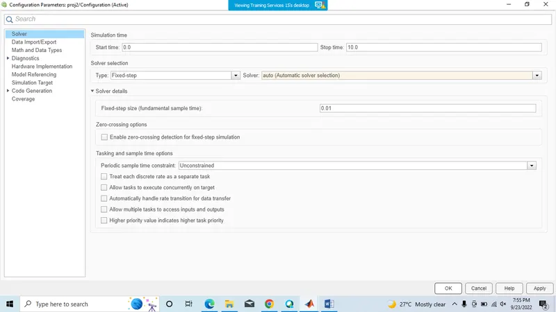
- Choose sample time for all signals as 0.01s.
Requirement 1– Lead Vehicle:
- Lead Vehicle is a vehicle which is driving in the road ahead of our drive vehicle. Two input signals (Signal Name: CameraInput_LeadVehicle & RadarInput_LeadVehicle).
- Ideally sensor fusion techniques will be deployed to process & analyze data from camera & radar. For complexity reasons, let’s not adapt to any such algorithms.
- We can simply add both the radar & camera inputs & the corresponding output is read as Speed profile output (Signal Name: LeadVehicle_Speed).
- Speed data of the lead vehicle is critical in implementing the Adaptive Cruise Control algorithm.
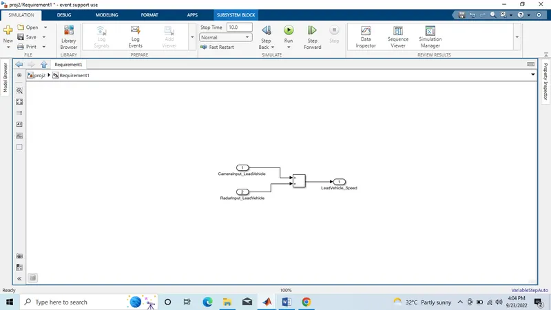
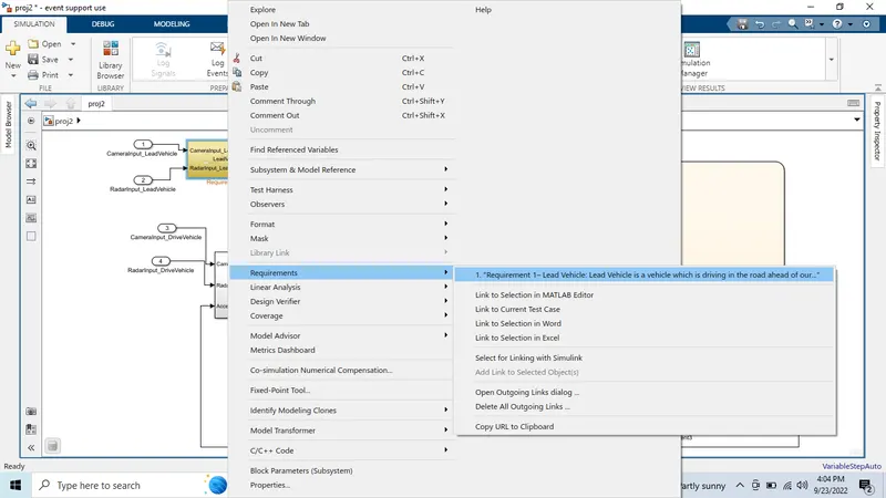
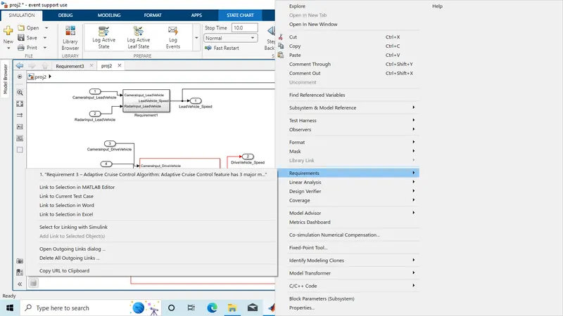
The above model is converted into subsystem names requirement 1. And the requirement is added into the subsystem.
Requirement 2 – Drive Vehicle:
- Drive Vehicle is the vehicle driven by the user & this is the vehicle which has ACC algorithm in it.
- Like the Lead Vehicle, Drive Vehicle algorithm also has 2 input signals (Signal Name: CameraInput_DriveVehicle, RadarInput_DriveVehicle) & one signal coming as an Input to this subsystem (Signal Name: Acceleration_Mode) – three inputs into this requirement in total.
- Like the above requirement, sensor fusion techniques will also be deployed here, for complexity reasons we are ignoring them.
- Two output signals come from this subsystem (Signal Name: DriveVehicle_Speed & LeadVehicle_Detected).
- Signal DriveVehicle_Speed is summation of three input signals mentioned above & LeadVehicle_Detected is renamed from Input Signal RadarInput_DriveVehicle by mere use of Signal Conversion block.
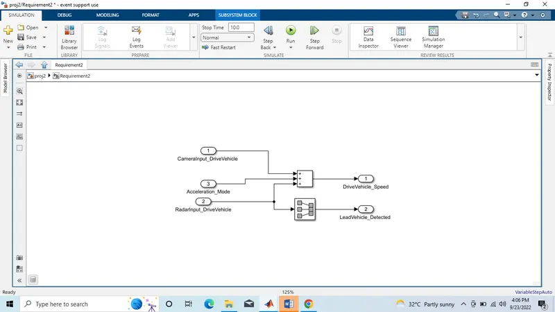
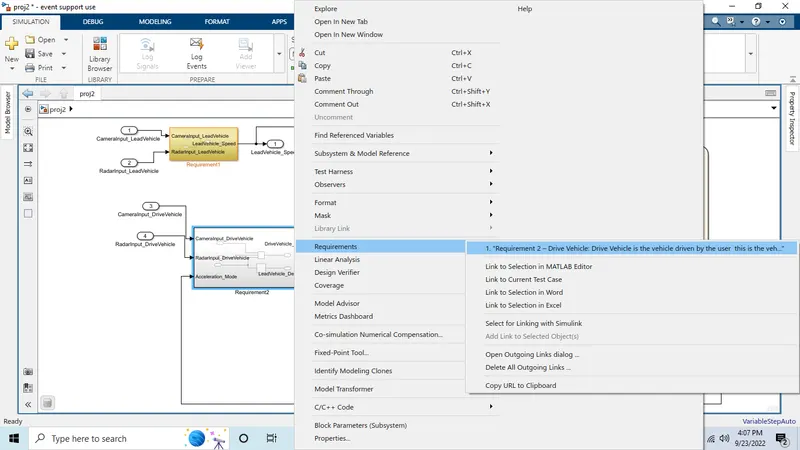
The above model is converted to subsystem named requirement 2 and the requirement in word is added to the subsystem.
Requirement 3 – Adaptive Cruise Control Algorithm:
- Adaptive Cruise Control feature has 3 major modes of operation: OFF Mode, STANDBY Mode & ON Mode. This particular requirement has to be implemented as state machine logic in Simulink.
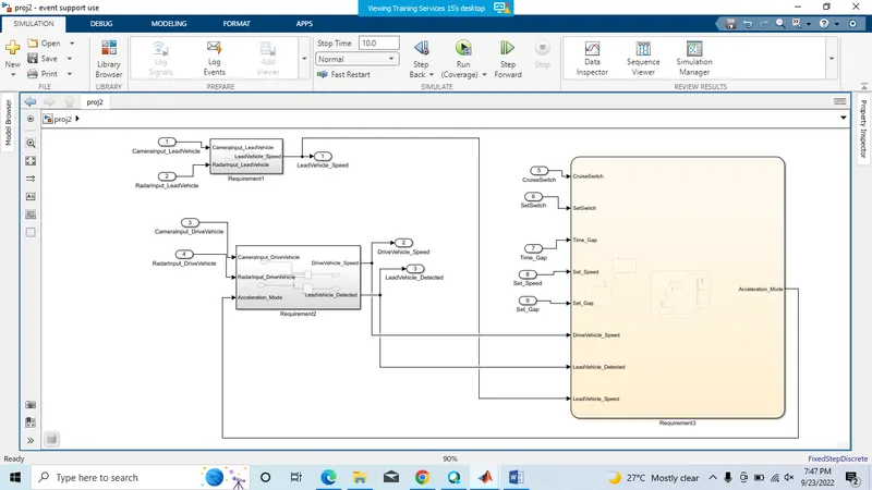
- The input signals to this state machine system are (Signal Name: Time_Gap, Set_Speed, Set_Gap, CruiseSwitch, SetSwitch).
- Also, the output signals (Signal Name: DriveVehicle_Speed & LeadVehicle_Detected) from requirement-2 is fed back as an input signal into this state machine block.
- Additionally, output signal (Signal Name: LeadVehicle_Speed) from requirement-1 is given as an input signal to this state machine block as well.
- Output from this subsystem is a signal (Signal Name: Acceleration_Mode) which governs the vehicular speed of the drive vehicle which automatically adjusts its speed & velocity to match the lead vehicle.
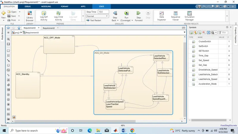
Requirement tagging 3
The final model is as shown below
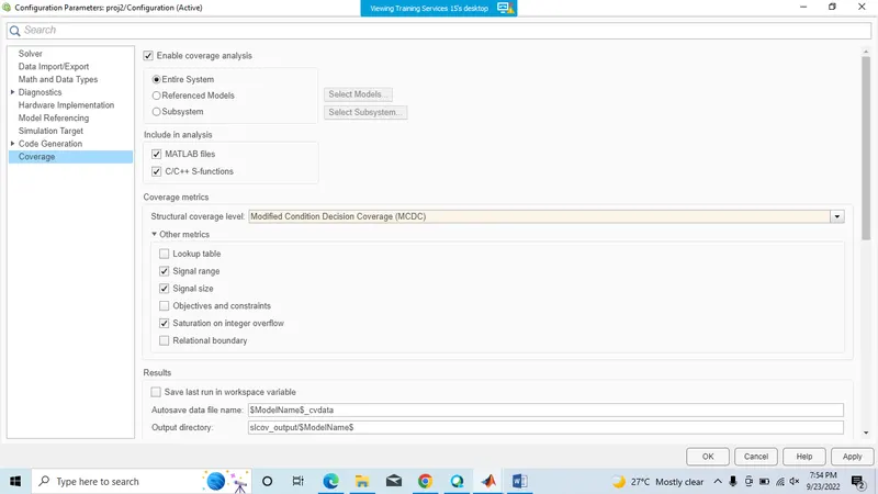
Model Configurations
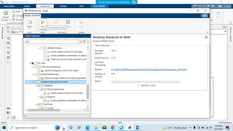
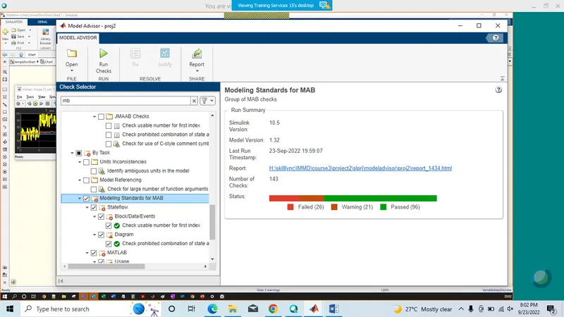
Model Advisor
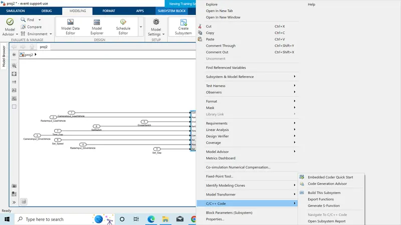
S function builder
/*
 * Event Support License -- for demonstration use and event support.  Not
 * for government, research, commercial, or other organizational use.
 *
 * File: Subsystem.c
 *
 * Code generated for Simulink model 'Subsystem'.
 *
 * Model version                  : 1.35
 * Simulink Coder version         : 9.7 (R2022a) 13-Nov-2021
 * C/C++ source code generated on : Fri Sep 23 20:22:22 2022
 *
 * Target selection: ert.tlc
 * Embedded hardware selection: Intel->x86-64 (Windows64)
 * Code generation objectives: Unspecified
 * Validation result: Not run
 */

#include "Subsystem.h"
#include "rtwtypes.h"

/* Named constants for Chart: '/Requirement3' */
#define IN_LeadVehicleNotDetectedResume ((uint8_T)4U)
#define IN_LeadVehicleSpeedEqualSetSpee ((uint8_T)5U)
#define IN_LeadVehicleSpeedLessThanSetS ((uint8_T)6U)
#define Su_IN_LeadVehicleDetectedFollow ((uint8_T)1U)
#define Su_IN_LeadVehicleDetectedResume ((uint8_T)2U)
#define Subsy_IN_LeadVehicleNotDetected ((uint8_T)3U)
#define Subsystem_IN_ACC_OFF_Mode      ((uint8_T)1U)
#define Subsystem_IN_ACC_On_Mode       ((uint8_T)2U)
#define Subsystem_IN_ACC_Standby       ((uint8_T)3U)
#define Subsystem_IN_NO_ACTIVE_CHILD   ((uint8_T)0U)

/* Block states (default storage) */
DW_Subsystem_T Subsystem_DW;

/* External inputs (root inport signals with default storage) */
ExtU_Subsystem_T Subsystem_U;

/* External outputs (root outports fed by signals with default storage) */
ExtY_Subsystem_T Subsystem_Y;

/* Real-time model */
static RT_MODEL_Subsystem_T Subsystem_M_;
RT_MODEL_Subsystem_T *const Subsystem_M = &Subsystem_M_;

/* Model step function */
void Subsystem_step(void)
{
  /* Sum: '/Add' incorporates:
   *  Inport: '/CameraInput_LeadVehicle '
   *  Inport: '/RadarInput_LeadVehicle'
   */
  Subsystem_Y.LeadVehicle_Speed = Subsystem_U.CameraInput_LeadVehicle +
    Subsystem_U.RadarInput_LeadVehicle;

  /* Sum: '/Add' incorporates:
   *  Delay: '/Delay One Step'
   *  Inport: '/CameraInput_DriveVehicle '
   *  Inport: '/RadarInput_DriveVehicle'
   */
  Subsystem_Y.DriveVehicle_Speed = (Subsystem_U.CameraInput_DriveVehicle +
    Subsystem_Y.Acceleration_Mode) + Subsystem_U.RadarInput_DriveVehicle;

  /* Chart: '/Requirement3' incorporates:
   *  Inport: '/CruiseSwitch'
   *  Inport: '/RadarInput_DriveVehicle'
   *  Inport: '/SetSwitch'
   *  Inport: '/Set_Gap'
   *  Inport: '/Set_Speed'
   *  Inport: '/Time_Gap'
   */
  if (Subsystem_DW.is_active_c3_Subsystem == 0U) {
    Subsystem_DW.is_active_c3_Subsystem = 1U;
    Subsystem_DW.is_c3_Subsystem = Subsystem_IN_ACC_OFF_Mode;
  } else {
    switch (Subsystem_DW.is_c3_Subsystem) {
     case Subsystem_IN_ACC_OFF_Mode:
      if ((Subsystem_U.CruiseSwitch == 1.0) || (Subsystem_U.SetSwitch == 0.0)) {
        Subsystem_DW.is_c3_Subsystem = Subsystem_IN_ACC_Standby;
      } else if (Subsystem_U.SetSwitch == 1.0) {
        Subsystem_DW.is_c3_Subsystem = Subsystem_IN_ACC_On_Mode;
        Subsystem_DW.is_ACC_On_Mode = Su_IN_LeadVehicleDetectedFollow;
      } else {
        /* Outport: '/Acceleration_Mode' */
        Subsystem_Y.Acceleration_Mode = 0.0;
      }
      break;

     case Subsystem_IN_ACC_On_Mode:
      if (Subsystem_U.SetSwitch == 0.0) {
        Subsystem_DW.is_ACC_On_Mode = Subsystem_IN_NO_ACTIVE_CHILD;
        Subsystem_DW.is_c3_Subsystem = Subsystem_IN_ACC_Standby;
      } else {
        switch (Subsystem_DW.is_ACC_On_Mode) {
         case Su_IN_LeadVehicleDetectedFollow:
          if (Subsystem_U.RadarInput_DriveVehicle == 0.0) {
            Subsystem_DW.is_ACC_On_Mode = Subsy_IN_LeadVehicleNotDetected;
          } else if (((Subsystem_U.RadarInput_DriveVehicle == 1.0) &&
                      (Subsystem_Y.LeadVehicle_Speed < Subsystem_U.Set_Speed)) ||
                     (Subsystem_U.Time_Gap < Subsystem_U.Set_Gap)) {
has popup