Answer: Mathematical modeling of the given motor schematic are as follows:
Applying Kirchoff's Law, as per kirchoff's closed loop law:
Ldi/dt + RI= V - Km dθ/dt..................(1) where; Back EMF(Vb)= Kb*w= Km dθ/dt
Now, as per newton's law:
Jd^2θ/dt^2 +B dθ/dt =Kt*I.............(2)
Applying Laplace Transform on equ(1)
L sI(s) +R I(s)= V(s) - Km s θ(s).............(3)
I(s)=V(s)- Km s θ(s)/L s + R................(4)
Applying Laplace Transform on equ(2)
J s^2 θ(s) + B s θ(s)= Kt *I(s)............(5)
w(s) = s θ(s)= Kt *I(s)/Js+B................(6)
Substituting equ(4) in equ(5):
J s^2 θ(s) + B s θ(s)= Kt* V(s)- Km s θ(s)/L s + R.....(7)
Hence Found : w(s)/V(s) = Kt/[(Ls +R) (Js +B) + (Kt *Km)]...........(8)
Equation for Speed Control of DC Motor Using PID Controller:
U(s)/E(s)=Kp+ Ki/s+Kd s......................(9)
Matlab code for finding out Kp and Kd:
clc;
clear all;
%Dynamics for open loop Transfer Function of the motor with the speed(w)
%and supply voltage(Vs): w(s)= V(S)*Kt/(J*s +B)(La*s+Ra)+(Kt*Km)
J=0.01; %moment of inertia of rotor in kg-m^2
b=0.1; %motor viscous friction constant in N-m-s
Km=0.01;%back EMF constant in v/rad/s
Kt=0.01; %motor torque constant in N-m/amp
Ra=1.0; %resistance of the armature circuit in Ohms
La=0.5; %inductance of the armature circuit in henries
A=[-b/J Kt/J;-Km/La -Ra/La];
B=[0; 1/La];
fn=1;
wn=2*pi*fn;
zeta=0.5;
p1=-zeta*wn+wn*sqrt(zeta^2-1);
p2=-zeta*wn-wn*sqrt(zeta^2-1);
P=[p1;p2];
K=place(A,B,P);
Result: Kp = 38.3133 and Kd= -2.8584
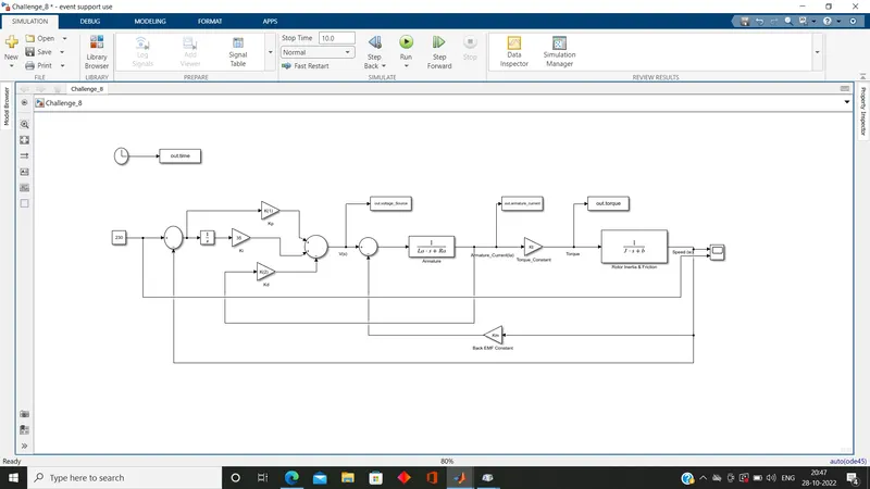
Simulink Model:
Description:(i)Very first Wrote the given motor schematic in mathematical form in time domain after that using the laplace transform change the equations in frequency domain and find out the Transfer Function as w(s)/V(s) = Kt/[(Ls +R) (Js +B) + (Kt *Km)].
(ii)Using the Transfer Function made the simulink model of the given motor schematic and write the matlab code for finding out Kp and Kd through pole placement method using place command.
(iii)Control the speed of DC Motor using PID Controller with armature current feedback with gain Kd and model the PID Controller as U(s)/E(s)=Kp+ Ki/s+Kd s.
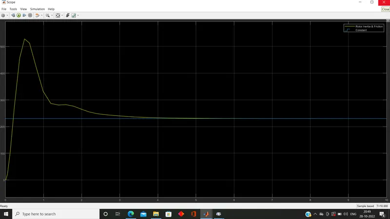
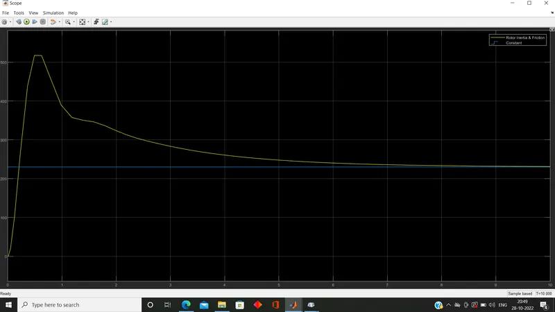
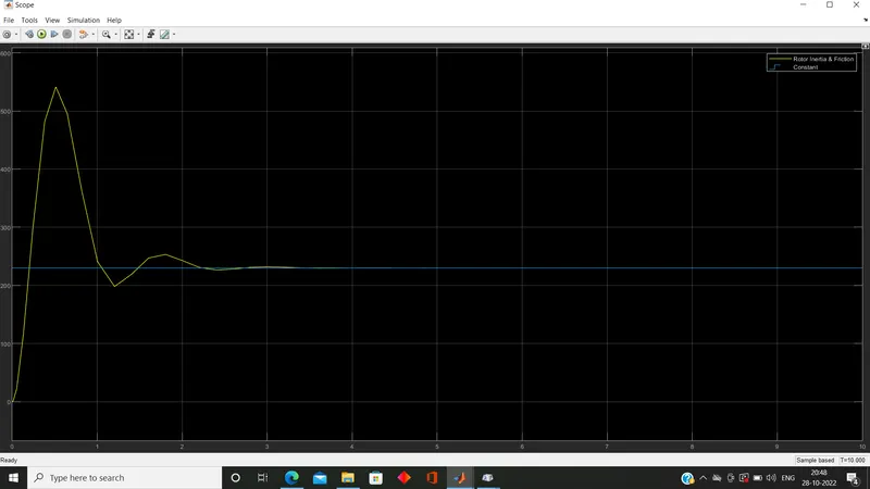
(iv)By varying 'Ki' achieved the perfect response of controller, which are as follows:
Result at Ki = 20:
Result at Ki= 10:
Result at Ki= 35:
Note: The Constant speed is 230 which has perfectly been achieved at Ki= 35 after one peak and settling time is 3sec., steady state error is zero and overshoot is 550-230=320 ; 320/100 = 3.2%.