Project 2 Adaptive Cruise Control
Objective of Main Project:
- Developing Adaptive Cruise Control feature as per the Requirement Document using MATLAB Simulink.
- Follow all the MBD related processes: Requirement Tagging & Traceability, SLDD creation, Configuration Parameter changes, Model Advisor check & Code Generation.
- In Configuration Parameters: enable “Support Floating Numbers” under Code Generation settings.
- Use Embedded Coder to generate the code.
- If choosing code generation, Storage class for Input signals: ImportedExtern; Storage class for Output signal: Export to File; Storage class for local signals: localizable; Storage class for calibration signals: Const.
- Choose sample time for all signals as 0.01s
Requirement 1– Lead Vehicle:
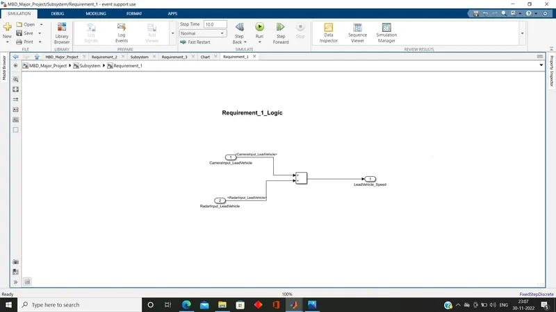
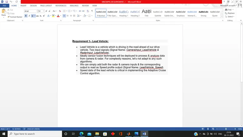
- Lead Vehicle is a vehicle which is driving in the road ahead of our drive vehicle. Two input signals (Signal Name: CameraInput_LeadVehicle & RadarInput_LeadVehicle).
- Ideally sensor fusion techniques will be deployed to process & analyze data from camera & radar. For complexity reasons, let’s not adapt to any such algorithms.
- We can simply add both the radar & camera inputs & the corresponding output is read as Speed profile output (Signal Name: LeadVehicle_Speed).
- Speed data of the lead vehicle is critical in implementing the Adaptive Cruise Control algorithm.
Steps Performed:
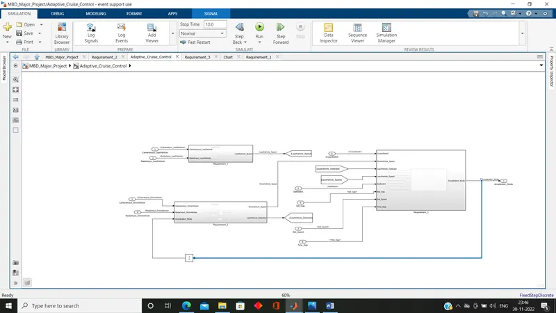
(i)Subsystems Creation: Created three Subsystems and named it as Requirement_1, Requirement_2 and Requirement_3.
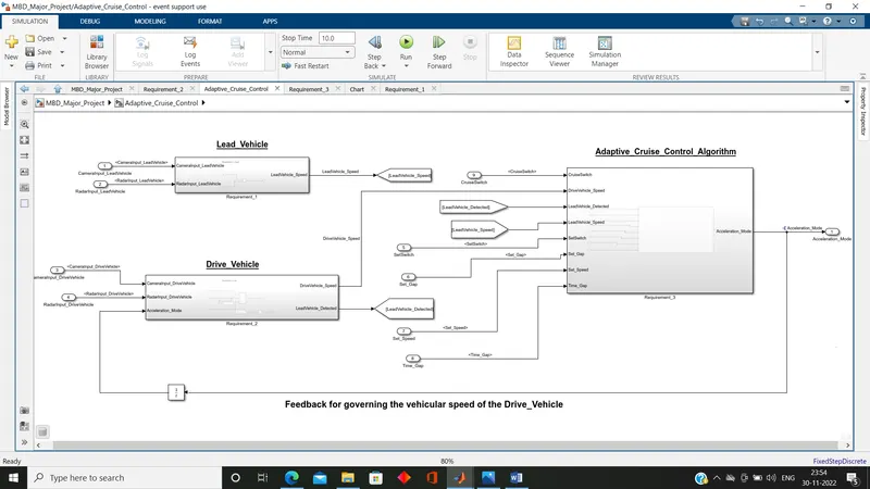
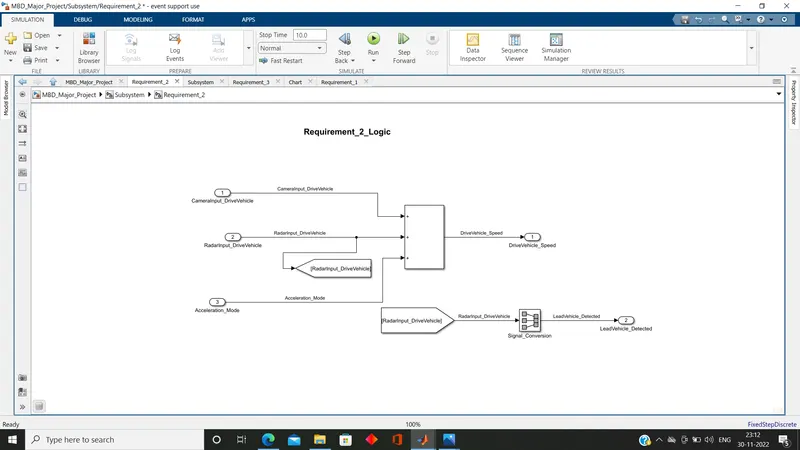
(ii)Build the logic as per given requirement-1, requirement-2 and requirement-3 and made the connections.
Note: for requirement_3 opened the chart and as given took three states ACC_OFF, ACC_STANDBY and ACC_ON. for ACC_ON further defined six states inside it. set all the condition and condition to transition as given, then opened the symbol pane and fixed the input and output parameters.
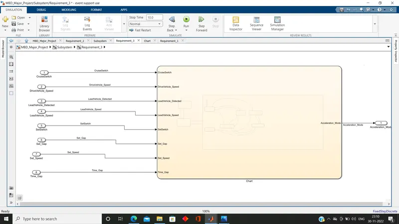
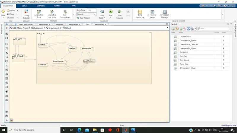
Photo: Cruise Control Algorithm in State_Machines
(iv)Unit Delay Connection: for feedback to Requirement_2 Subsystem Block from final output as Acceleration_Mode from Requirement-3 Subsystem. (It governs the vehicular speed of the drive vehicle which automatically adjusts its speed & velocity to match the lead vehicle.)
(iii)SLDD Creation: Created a SLDD using given signals & calibration Data List. (Under model explorer tab open linked to data dictionary and named the SLDD file as mbd_majorproject and saved it.)
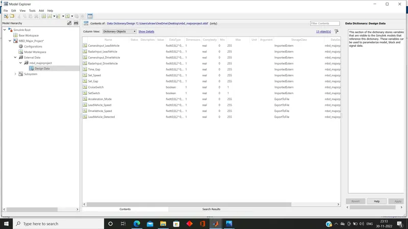
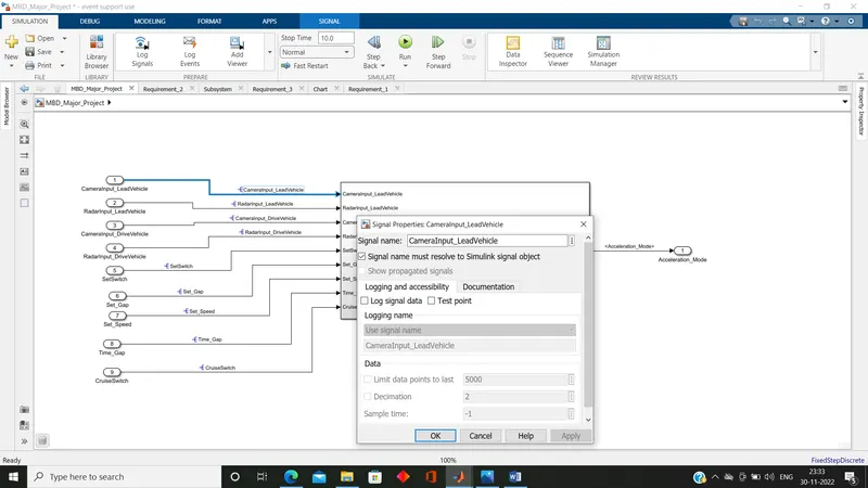
(iv)Signal Resolving and Propogation: at the input end resolved the signals and at the output end propogated.
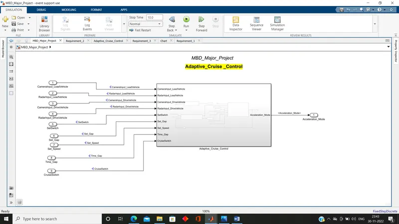
(v)Selected all the three subsystems and created a single subsystem.
(v)Requirement Tagging:
(a)Pasted given Requirement-1 in a Word Document and saved it, similarly for Requiremt-2 &3.
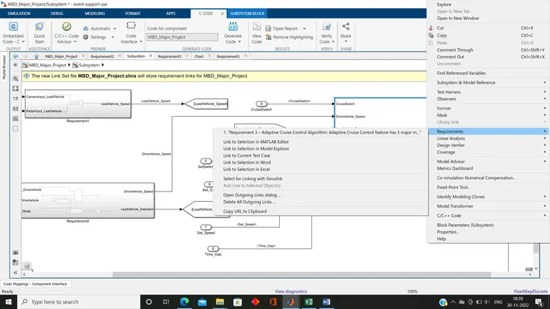
(b)Taggigng Requirement in Model: Open the saved word document and copied the given requirement, went to the concern subsystem then Selected and press the right click, went into requirement and chose link to selection in word.(Performed similar operation for all three subsystem)
(vi)Configuration: Press the cntrl+E and went into configuration parameter, opened the solver and made the selection Type as fixed step and solver as Discrete(no continuous state) and step size as 0.01 also, selected embedded coder and ensured “Support Floating Numbers” under Code Generation is enable.
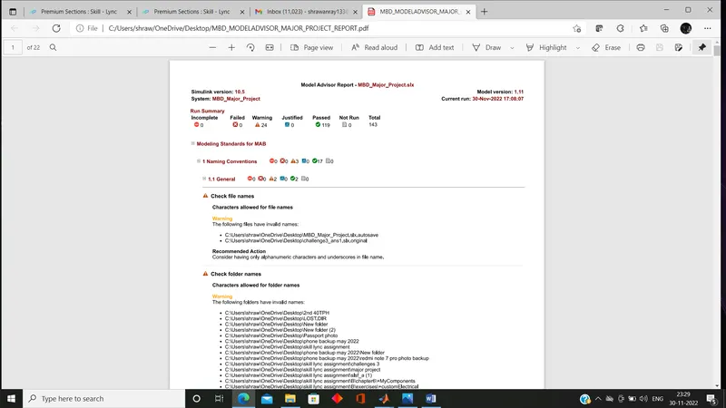
(vi)Model Advisor Report: Hit on the model advisor and created report using generated link and saved it in a pdf.
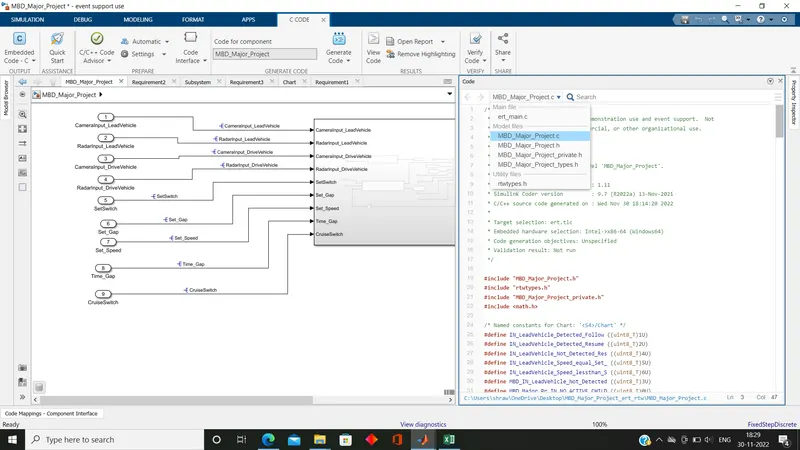
(vii)Code Generation: under APP tab went into embedded coder select the code generation and generated code and code generated in four types: .c , .h, private.h and types.h.