Project AIM: To dvelope a simulink model of a DC motor and to design PID control to obtained desired speed of DC motor
Theory and Procedure:
Mathematical modelling of a DC motor as per schematic:
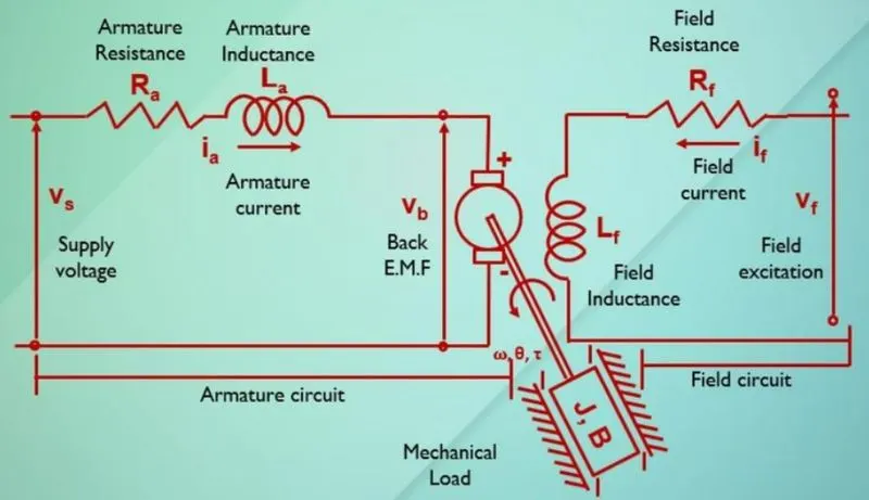
From the above schematic diagram we can see that,
Vs = Ra*ia + La*d(ia)/dt+vb
where,
vb=Km*d(theta)/dt
and Tou(t)= Kt*ia
where, Km is back emf constant and Kt is torque constants
w is angular velocity
when we apply laplas transform on equations we got
w(s)/Vs(s)=Kt/(J*La*S^2)+(J*Ra+B*La)*S+(B*Ra+Km*Kt)
% DC motor Design Parameters
J = 0.01; %Inertia
B = 0.1; %Friction
Kb = 0.01; % Back EMF constant
Kt = 0.01; %Torque constant
Ra = 1; %Armature Resistance
La = 0.5; %Armature Inductance
using above parameters Dc motor is designed
Armature inductance can be written in laplas transform as 1/(La*S+Ra) this is electrical component of a DC motor
and rotor Inertia and friction components can be written in laplas transform as 1/(J*S+B) this is mechanical components of a DC motor where J is inertia and B is friction of motor components
DC motor simulink model :
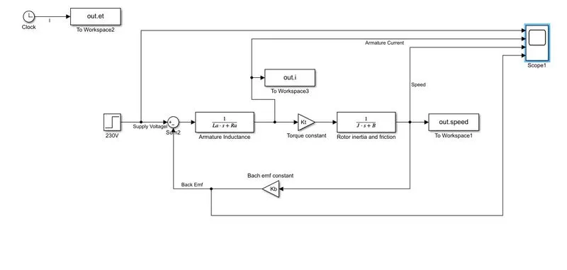
As per schematic DC motor is designed in simulink and various parameters of a DC motor are observed as below
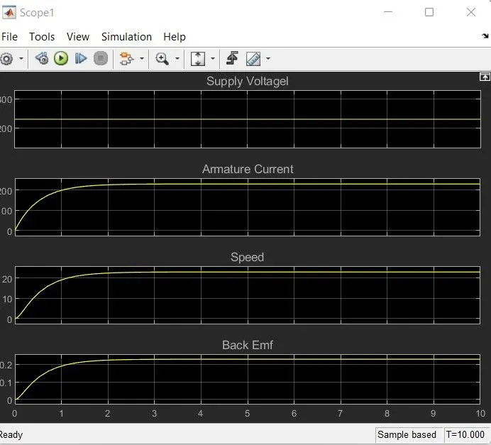
as we can see that very large amount of Armature current is drawn hence another resistance is attched in series with armature resistance to reduce starting current.
PID Controller for speed control of DC motor :
To design a PID control of a DC motor we need Eigen vectors A and B of a DC motor
A = [-B/J Kt/J; -km/La -Ra/La]
and B matrix is = [0; 1/La]
to find Proportional and derivative gains pole placement method is used for that we need to conside following factors
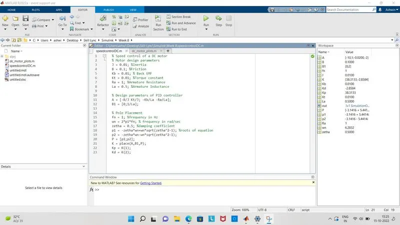
% Design parameters of PID controller
A = [-B/J Kt/J; -Kb/La -Ra/La];
B1 = [0;1/La];
% Pole Placement
fn = 1; %frequency in Hz
wn = 2*pi*fn; % frequency in rad/sec
zetha = 0.5; %damping coefficient
p1 = -zetha*wn+wn*sqrt(zetha^2-1); %roots of equation
p2 = -zetha*wn-wn*sqrt(zetha^2-1);
P = [p1;p2];
K = place(A,B1,P); %place commandd is used to plot the poles
Kp = K(1);
Kd = K(2);
in this way Kp and Kd are obtained and Intergral gain Ki is need to be assumed to maintain response within proper limits,
here for Zetha=0.5 we got
PID control simulink Model:
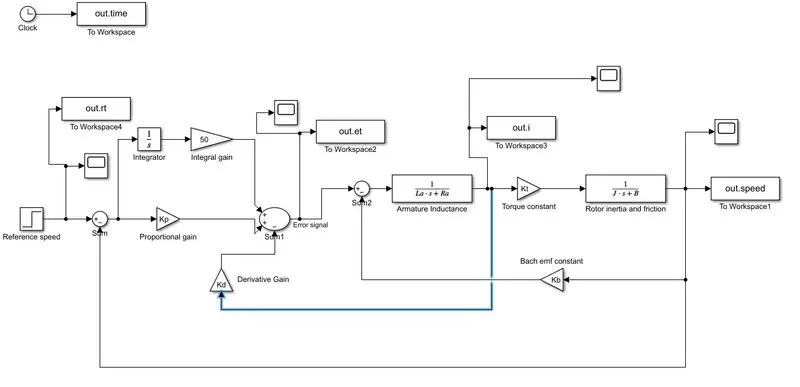
In this model we can see that a reference speed is considered as 100 and PID control is designed to have speed control
Now for various values of Ki system is analysed for best tracking response as shown below
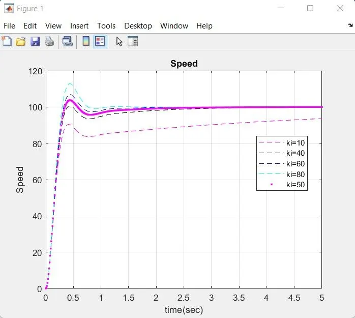
We can see from the above plots that for values of
Kp=38.3133
Kd=-2.8584
Ki=50
system shows best response for speed control means peak overshoot, settling time, rise time are within limits and shows minimal damping.
Result:
1) A DC motor is designed with design paramets and its performance is shown in graphs.
2) PID control for speed control of a DC motor is designed for zetha=0.5 and kp,kd,ki gains are evaluated with the help of pole placement method and best tracking response is demonstrated using simulink model.
********************************************XXXX*************************************************