Project - Position control of mass spring damper system
Aim:
Obtain the transfer function of a mass spring damper system and use it in the model. Add a PID controller to adjust the force on mass so that its position follows a reference signal.
Take m = 3.6; %kg k = 400; %N/m c = 100; %Ns/m
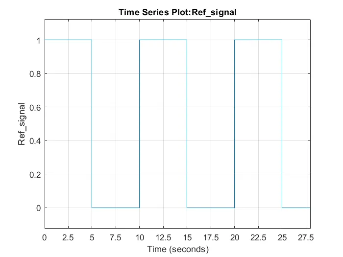
The reference signal is shown in the following figure.
System design:
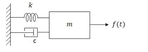
we know the transfer function of mass spring damper system
f(t)-cdx/dt-kx(t)=mdx^2/dt^2
Byapplying laplace transform
F(s)-csX(s)-kX(s)=ms^2X(s)
T(s)=1/ ms^2+Cs+k
we know the second order transfer function
T(S)=wn^2/(s^2+2*z*wn*s+wn^2)
by comparing above equation
1/ ms^2+Cs+k=wn^2/(s^2+2*z*wn*s+wn^2)
we got wn=sqrt(1/m)
zeta,z=c/2*wn*m
We know that state space model for mass spring damper system
and we can find pole using below equation
From above details we can find controller gain using place commands
Matlab program for finding controller gains are shown below:
clc;
clear all;
%Given parameters of the spring mass system
% mass of the spring mass system
m = 3.6; %kg
k = 400; %N/m
c = 100; %Ns/m
%calculated Data
f =1;
wn = sqrt(1/m);
z=(c/(2*wn*m));
%System matrix finding A and B matrix
A = [0 1;-k/m -c/m];
B = [0;1/m];

%Finding the poles
p1 = -wn*z+wn*sqrt(z^2-1);
p2 = -wn*z-wn*sqrt(z^2-1);

%creating pole matrix
p = [p1;p2];

%finding the gain matrix K
K = place(A,B,p)
Kp=K(1)
Kd=K(2)
Ki=1000;Simulation:Simulation of given mass spring damper system is shown as below
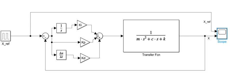
Block used:Pulse generator,sum,integrator,derivative,Transfer function and scope
- Blocks are connected as shown here we substract the output signal from reference signal and we got error signal we gave the error signal to a PID controller to improve the output value
Procedure:
- Pulse generator output set as given in the question shown below which is used as input signal
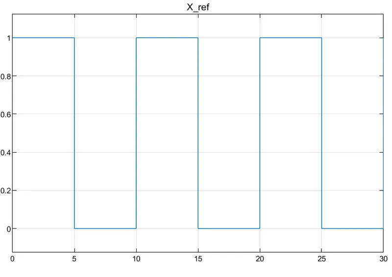
- Run the program for 30s
Result:Obtained the output from comparing different gain value
Case1:
- Output from scope by using Kp Kd from place command and given Ki=2
Kp=-399 Ki=2 Kd= 1.2790e-14
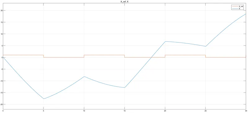
- The output doesnt follow the reference signal
Case2:
Kp=1000 Ki=15000 Kd=95
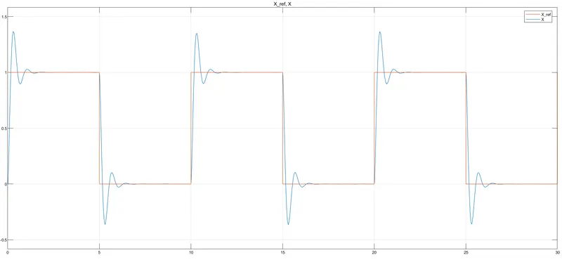
- with These gain value Output is almost similar to input but some overshoot ans oscillations are present
Case3:
Kp=2600 Ki=15000Kd=96
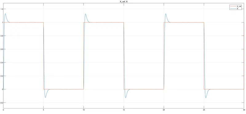
- With these set of Kp Ki and Kd we can obseverd that output is following input reference signal
CONCLUSION:
Obtained the transfer function of a mass spring damper system with m = 3.6kg k = 400 N/m c = 100 Ns/m using matlab programming and Created a transferfunction model and added PID controller and adjusted the force on mass so its position follows a reference signal when Kp=2600 Ki=15000 and Kd=96