Project - Position control of mass spring damper system
OBJECTIVE
To design and analyses a mass spring damper system with PID control, utilizing the given parameters.
INTRODUCTION
This report presents the design and analysis of a mass spring damper system with a PID controller. The objective is to design a control system that ensures the force follows a reference signal while minimizing overshoot, reducing settling time and improving overall system stability. The system parameters are as follows:
Mass = 3.6 kg
Spring constant = 400 N/m
Damping coefficient = 100 Ns/m
Reference signal: pulse generator with an amplitude 1 and period 10s
SYSTEM MODELLING
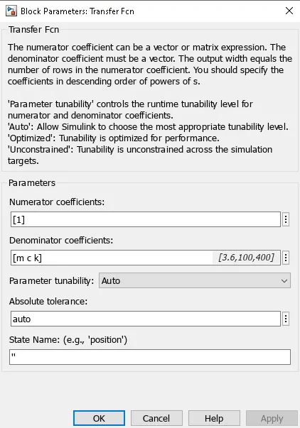
Transfer Function
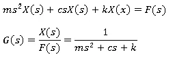
The equation of motion for the system is

Taking Laplace transform
Controller Design
Gains for this Simulink model were calculated using this MATLAB program.
% Design parameters
m = 3.6; % Mass
k = 400; % Spring constant
c = 100; % Damping coefficient
% Calculating proportional gain and derivative gain
Wn = sqrt(k/m);
fn = Wn/(2*pi);
zeta = 0.8; % Almost critically damped
p1 = -zeta*Wn + Wn*sqrt(zeta^2 - 1);
p2 = -zeta*Wn - Wn*sqrt(zeta^2 - 1);
A = [0 1; -k/m -c/m];
B = [0; 1/m];
p = [p1; p2];
K = place(A,B,p);
Kp = K(1);
Kd = K(2);
% Integral gain
Ki = 500;
Using this proportional gain and derivative gain are found. Integral gain is set manually
SIMULINK MODEL
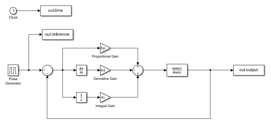
The Simulink model is modeled using the blocks
Pulse generator: provides reference input to the system
Gain block: implement gains to the model
Derivative block: simulates the derivative operations
Integrator block: simulates the integration operations
Transfer function block: represents the dynamics spring mass damper system
Sum block: combines signals
To workspace block: export the simulation data to MATLAB workspace
Using these blocks the PID controlled spring mass damper system is modeled as shown below.
RESULTS
When Ki = 0
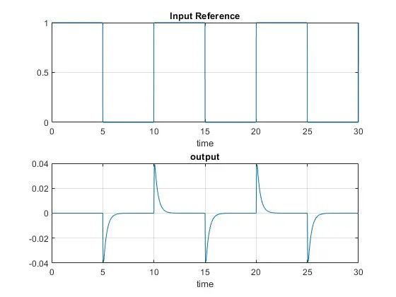
The steady state error is significantly high, as the output remains close to zero. This shows the systems inability to track the reference signal effectively
When Ki = 500
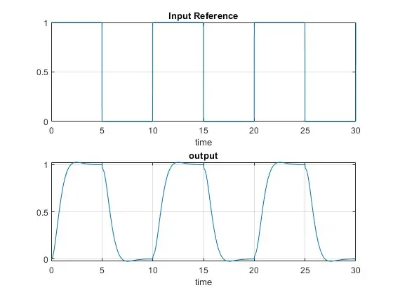
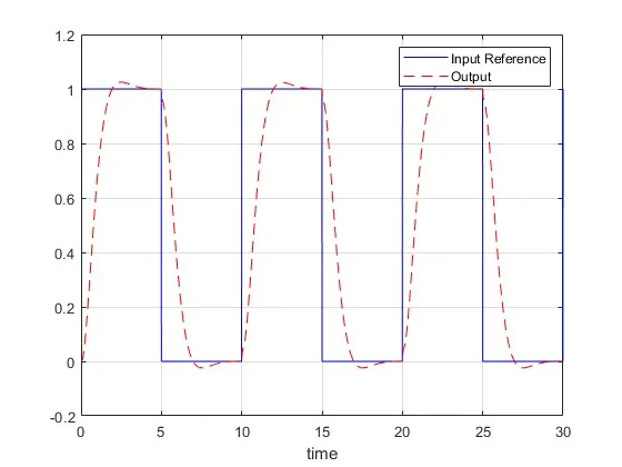
With an increased integral gain, the system shows good improvement in steady state performance. After an initial overshoot, the output stabilizes and accurately tracks the reference signal.
CONCLUSION
The design of PID controlled spring mass damper system was successfully completed. The system is able to track the reference signal, with an initial overshoot and stabilizes at the desired value. Increasing the integral gain improved steady state performance by eliminating the steady state error, showing the importance of tuning all three PID parameters for optimal condition.