Project - Position control of mass spring damper system
Ans] Mass spring damper system :
A mass-spring-damper system comprises masses, mechanical springs and parallel attenuators. The system can store potential and Kinetic energy.
Mass-spring-damper systems are primarily intended to reduce the transmission of vibrations and structure-borne noise. The flexible elements (springs) ensure the masses are decoupled in terms of Oscillation transmission. Mass and spring dynamics must be coordinated for this purpose.
The spring has a spring constant, a length at rest and a decay constant. If the spring is in the rest position, the system is also in its original position. If a mass is moved, the spring accumulates potential energy. that is minimized through displacement of the other mass points. The attenuator ensures that the system does not continue to oscillate after deformation but returns to its rest position. Weak, subcritical Damping leads to oscillation decay, while critical/supercritical damping leads to Creep decay.
A simple Mass-Spring-Damper system is show in figure .there for the Differential equation for system is .
f = m*a
where f = force , m= mass , a= acceleration
if x represent the displacement, x_dot represent the velocity and x_dot_dot represent the acceleration .Here the dot represent the time derivative.
f = m* x_dot_dot
in reality dynamic system should consider the damping manifested by the medium operating with it's associated stiffness.
f(t) = m* x_dot_dot +c*x_dot+k*x
where c = damping coefficient
k = stiffness constant
In MATLAB and Simulink the differential equation are converted into algebric equation by using the Laplace transferms [by doing this we making easy to solve ]
The Laplace transform of fuction f(t) is defined as
f(s) = m*s^2*X(s) + c*s*X(s) + k*X(s)
where f(s) =( m*s^2 +c*s+k)X(s) s = Laplace variable
X(s) = is the Laplace transform of fX(t)
f(s) = Laplace transform of f(t)
now X(s)/f(s) = 1/m*s^2 + c *s + k ..............................equation (1)
What is a PID Controller?
Proportional Integral Derivative (PID) controller is an automatically optimized and accurate control system used to regulate different parameters like temperature, pressure and speed at desired values. The basic mechanism used in PID controllers is control loop feedback. A PID calculates the error by calculating difference between actual value and desired value and then sets the deciding parameters accordingly. This error is continuously being calculated until the process stops.
Proportional is used to find out the error between the desired value and actual value and is responsible for the corrective response. Integral is applied to calculate all the past values of error and then integrate them to find out the Integral term. When error is expelled from the system this integral stops increasing. The derivative is used to predict the expected error values in future based on the present values. Controlling effect can be increased if the system has a rapid rate of change, which is also based on Derivative. Combining all these three operations gives the name Proportional Integral Derivative (PID) Controller.
u(t) = Kp e(t) + Ki int e(t)dt + Kd de(t)/dt
Kp is the coefficient of Proportional term.
Ki is the coefficient of integral term.
Kd is the coefficient of derivative term.
e(t) error between the referance input and measure output
gains are designed such that certain time domin (eg. rise time ,setting time ,overshoot and state error)
Rise time Tr = time required for the response to rise from 10% of final value to 90%
setting time Ts = time required for output to settle within a certain percent of it's final value and specified in terms of time constant (tua T), where T(tua) = 1/zeta*wn and a typical settling time Ts = 4/zeta*wn
Overshoot = The maximum deviation of excursion of the response abou the steady value.
Steady state error (Ess) = hang - off error between the desired steady state value and the actual steady state value .
There are two ways to defined PID controller .
1) we can make a model for that we have to use three gain block kp,kd and ki as shown
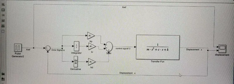
a) we used pulse Generator as Xref having
Amplitude =1 ,
Period (secs)=10 ,
Pulse Width (% of period)=50,
Phase delay (secs)=0 we used sum block to substract Displacement to make error signal
b) we give error signal e as input to all three gain kp, ki and kd
c) for integrator gain ki'' we gave the one integrator block
d) for derivative gain 'kd' we gave one derivative block
e)we used sum block to combined all three gain and out put of sum block to transfer fun {1/m*s^2 +c*s + k}
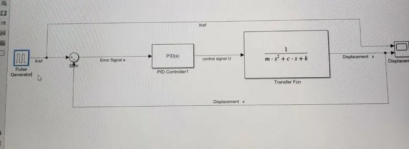
2] The Mathwork made is easy and more accurate we can use the PID block from continuous library whole the model remain same only we have to change the kp,ki and kd gain to PID block as shown
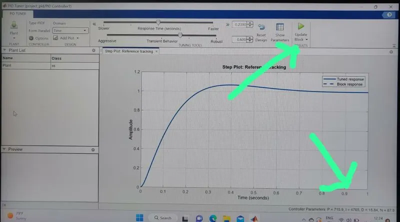
A] by double clicking the PID block and in right bottom tuner you cant cat the besr value of kp,kd and kp.
B] when the tued response solid line overlaped the Block response doted line you will get the controller parameters at right bottom corner and you can apply these parameters by clicking right top option ---Update Block as shown
C] After runing the model for 30 sec having values of
proportional gain kp=715.873738833498
integral gain ki = 4765.42583436529
Derivative gain = 15.8369058420836
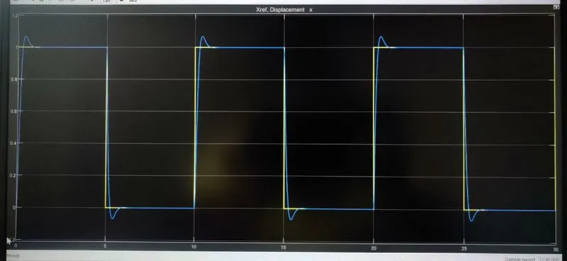
we got the ans