Project - Position control of mass spring damper system
Project - Position control of mass spring damper system:
Aim:
- Design a control system to regulate the position of a mass in a spring-damper system.
- Utilize MATLAB Simulink to model the transfer function of the mass-spring-damper system.
- Incorporate a PID controller to adjust the force applied to the mass, ensuring it tracks a specified reference signal for position.
Essential Components:
- Mass-Spring-Damper System Model: Represent the physical system using a transfer function in Simulink.
- PID Controller: Implement a Proportional-Integral-Derivative controller to calculate and apply the necessary force to the mass.
- Reference Signal: Define a desired position trajectory that the mass should follow.
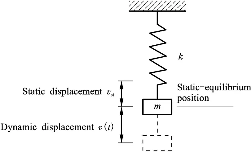
Procedure:
- Model the Mass-Spring-Damper System:
- Develop a Simulink model representing the dynamic behavior of the mass-spring-damper system.
- Utilize transfer functions to describe the relationship between force, position, and velocity.
Integration and Testing:
- Combine the mass-spring-damper model and the PID controller in a single Simulink model.
- Simulate the system to verify that the mass position tracks the reference signal accurately under various conditions (e.g., different reference trajectories, disturbances).
Expected Outcome:
- A functioning control system capable of regulating the position of the mass in the spring-damper system.
- The system should demonstrate the ability to follow reference position signals accurately and reject disturbances effectively.
- Through simulation, validate the stability and robustness of the control system design.
Significance:
- The project aims to showcase the application of control theory principles in real-world systems.
- It provides insights into the design and implementation of feedback control strategies for improving system performance.
- The developed control system can potentially be extended and adapted for use in various engineering applications requiring precise position control.
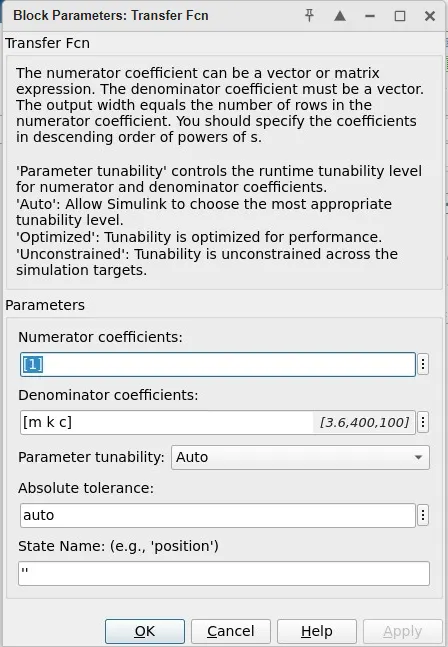
Transfer Function of Mass-Spring-Damper System:
- We'll incorporate the dynamic behavior of the mass-spring-damper system into the Simulink model using a transfer function.
- This transfer function represents the relationship between the force applied to the mass and its resulting position.
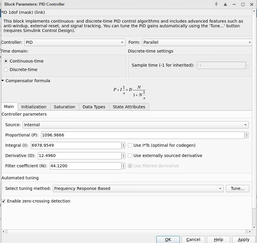
PID Controller Design:
- The PID controller will continuously adjust the force applied to the mass based on the error between the desired position (reference signal) and the actual position of the mass.
- Tuning of the PID controller parameters (Proportional, Integral, and Derivative gains) will be performed to achieve desired response characteristics.
- The controller aims to minimize the difference between the reference signal and the actual position of the mass by adjusting the force applied to it.
Implementation Steps:
Modeling the Mass-Spring-Damper System:
- Use Simulink to create a model of the mass-spring-damper system, incorporating its transfer function.
- Specify initial conditions, such as the initial velocity of the mass.
Designing the PID Controller:
- Integrate a PID controller block into the Simulink model.
- Tune the PID controller parameters to achieve the desired response characteristics, such as settling time, overshoot, and steady-state error.
- Ensure the PID controller generates a control signal that adjusts the force applied to the mass.
Combining the System and Controller:
- Connect the PID controller output to the input of the Force Source block in the Simulink model.
- Establish feedback from the mass position to the PID controller input to compute the error signal.
Testing and Validation:
- Simulate the integrated Simulink model to observe the response of the system to different reference signals.
- Verify that the mass position closely follows the reference signal with the desired performance characteristics specified by the PID controller tuning.
Significance and Benefits:
- The project demonstrates the practical application of PID control in regulating the position of a mechanical system.
- Through Simulink, various control algorithms and tuning parameters can be easily tested and optimized.
- This project provides a platform for exploring different control strategies and understanding their effects on system behavior.
Parameters for Position control of mass spring damper system:
Program script Explanation:
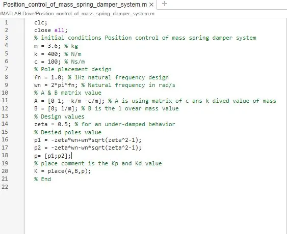
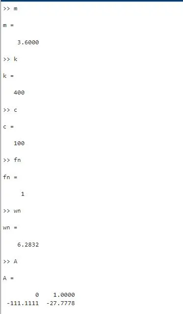
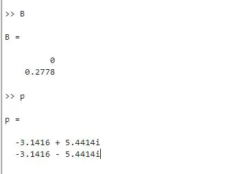
- The script is for controlling the position of a mass-spring-damper system.
- It starts by defining the system parameters: mass (m), spring constant (k), and damping coefficient (c).
- Pole placement design is used for controller design, aiming for a natural frequency of 1 Hz (fn).
- The natural frequency in radians per second (wn) is calculated using the formula wn = 2pifn.
- A and B matrices are defined based on the system parameters. A describes the system dynamics, while B represents the input influence on the system.
- The desired damping ratio (zeta) is set to achieve under-damped behavior.
- Desired poles (p1 and p2) are calculated based on the damping ratio and natural frequency.
- The place() function is used to compute the feedback gains (Kp and Kd) to place the poles at the desired locations.
- The script ends.
Simulink model:
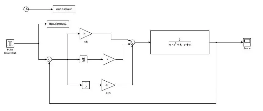
Plot Output:
Conclusion:
Successfully complted the project of Position control of mass spring damper system transfer function of a mass spring damper system and use it in the model. Add a PID controller to adjust the force on mass so that its position follows a reference signal to using matlab and simulink wave from plot.