Project - Position control of mass spring damper system
Ques No - 1 :-
Obtain the transfer function of a mass spring damper system and use it in the model. Add a PID controller to adjust the force on mass so that its position follows a reference signal.
Take m = 3.6; %kg k = 400; %N/m c = 100; %Ns/m
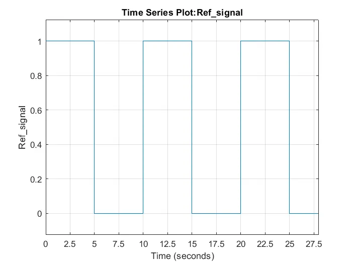
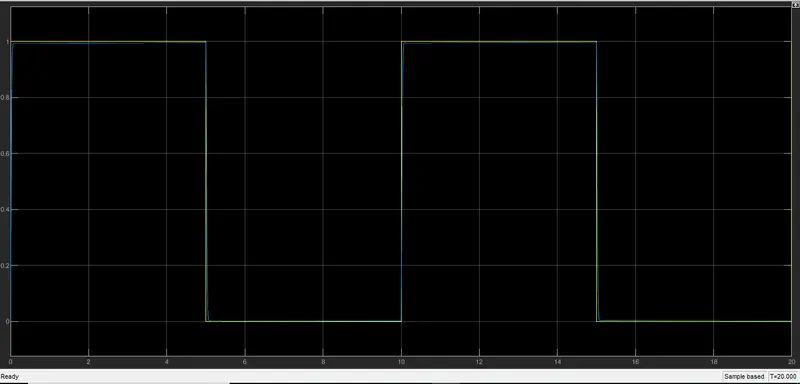
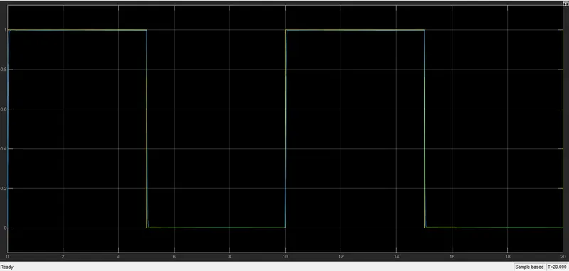
The reference signal is shown in the following figure.
Ans - Various Parameters used in creation of simulink model:-
1) Gain - It multiplies the value with a constant block.
2) Scope - It is used to display a signal as a function of time.
3) Pulse Generator - The Pulse Generator Source Block generates a pulse train of varying duty cycle. The signal switches between 0 and the specified value starting at a particular time. The Period, Duty Cycle, Amplitude, and Start Time can be specified
4) Gain - It multiplies the value with a constant block.
5) Sum - The Sum block performs addition or subtraction on its inputs. This block can add or subtract scalar, vector, or matrix inputs. It can also collapse the elements of a signal.
6) Integrator- The output of the Integrator is the integral of the input. An initial condition can be specified, as well as saturation limits. This block is very useful for modeling in simulink.
7) Transfer Function - It will help in modifying its input signal and outputs a new signal on a line to the Scope.
8) Derivative - It will approximates the derivative of the input signal u with respect to the simulation time t.
Model Parameters - Start Time - 0 sec , Stop Time = 20sec, Solver - ODE4 ( Runga Kutta) , step - size = 0.01
Pulse Generator Block Parameters:- 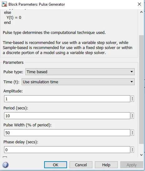
2) Transfer Function for a given system is given by the formula = 1/(m*s^2+c*s+k) , m is mass, c is damping coefficient , k is spring constant
m= 3.6 kg
k = 400 N/M
c = 100 Ns/m
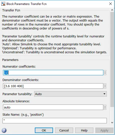
% Given Parameter for spring mass damping system
m= 3.6;
k= 400;
c= 100;

% Calcualtion of wn & fn
wn = k/m;% sqrt(k/m) in rad/sec
fn = 1.0;    % wn/(2*pi) in Hz
zeta = 0.9;

% Calculation of desired Poles
p1= -zeta*wn+wn*sqrt(zeta^2-1);
p2= -zeta*wn-wn*sqrt(zeta^2-1);
p=[p1;p2];

% For A & B Matrices
A= [0 1; -k/m -c/m];
B= [0; 1/m];

% Design of Pole placement
K = place(A,B,p);
kp = K(1)
kd = K(2)

%  Calculation of Transfer Function

% T = 1/(m*s^2 + c*s+k);
>> Project

kp =

   4.4044e+04


kd =

  620.0000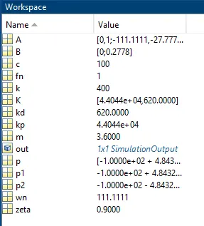
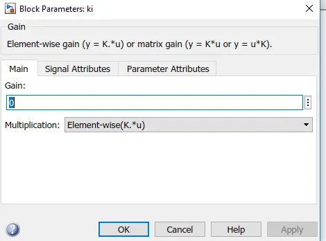
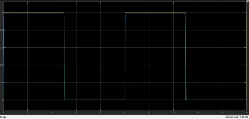
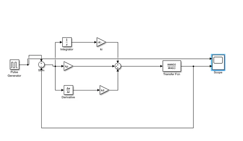
Simulink Model:-
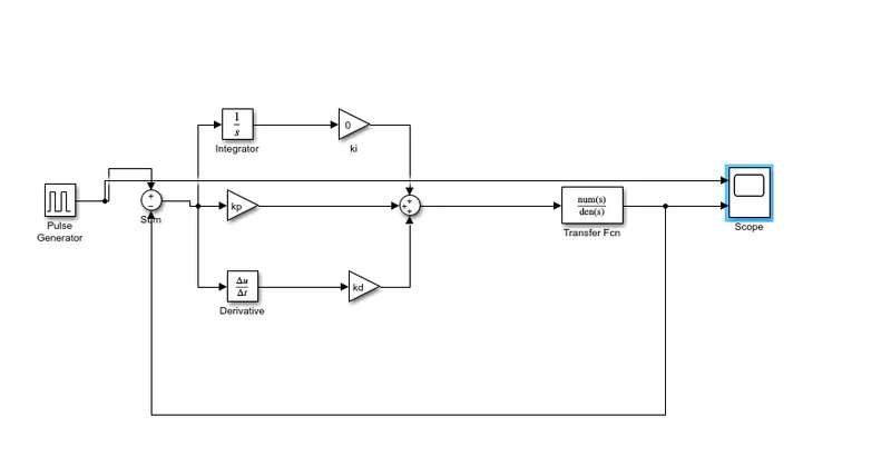
Observation : - steady state error is observed amid reference signal & simulated signal
2) Case - when Ki = 5000:-
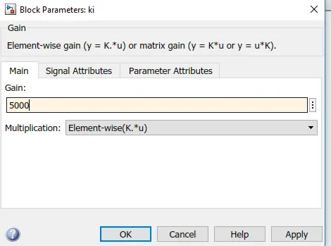
Simulink Model:-
Observation - steady error is reduced at ki = 5000 when ki = 0:-
3) Case - When Ki = 10000:-
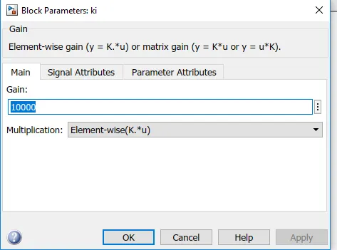
Simulink Model:-
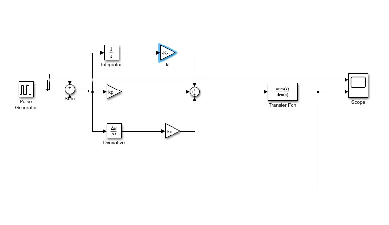
Conclusion :- With increase in value of ki steady state error continuously decreases .