Project - Position control of mass spring damper system
AIM :
Obtain the transfer function of a mass spring damper system and use it in the model. Add a PID controller to adjust the force on mass so that its position follows a reference signal.Take m = 3.6; %kg k = 400; %N/m c = 100; %Ns/m
OBJECTIVE :
Transfer function of a mass spring damper system and use it in the model. Add a PID controller to adjust the force on mass so that its position follows a reference signal.The matlab model of the PID control and transfer function pulse wavefrome generator. And also analyse the system stablity of transfer function
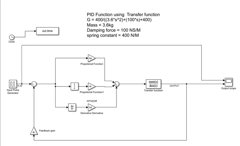
This simulink function shows a controlled mass-spring-damper system. The output of the function varies the input pulse signal.
Explanation:
Blocks used : Transfer function,Gain,Pulse generator,gain,sum and scope blocks.
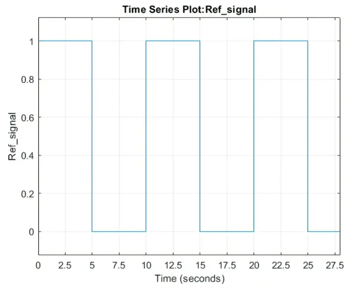
Input signal using pulse generator
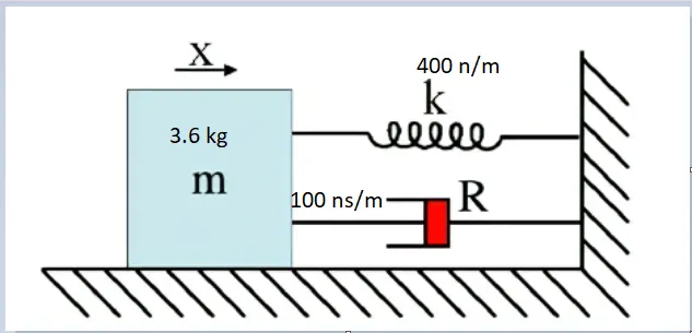
Spring mass damper system:
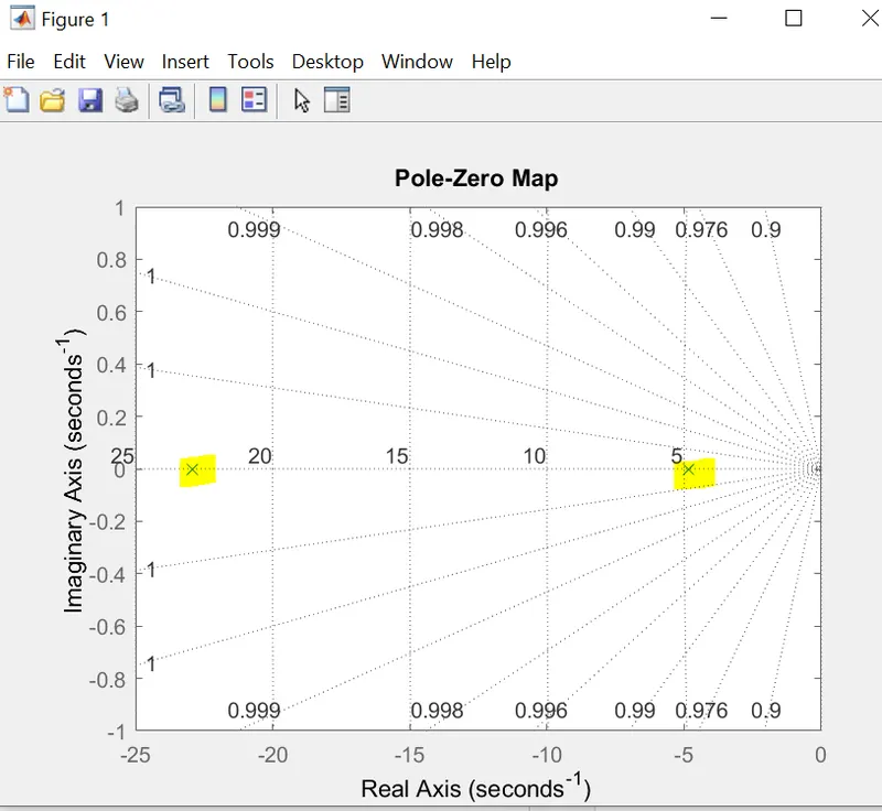
Stability
System stability was analysed using pzmap(G); function.Poles are on the left hand side of the palne.So Transfer function is stability
s = tf('s');
G = 400/((3.6*s^2)+(100*s)+400);
pzmap(G);
PID:
PID is the feedback closed loop control system to control the output.
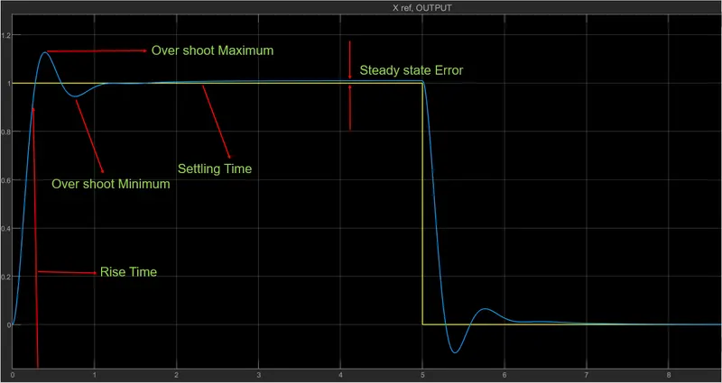
PID function is used achive the desired out put with correct Rise time,Settling time,Over shoot and stady state error.( ie to achive will give the bounded input wili het the bounded output)
PID controller:
In this project, PID controller has been designed by using Simulink in order to control a mass spring damper system.Ti interface the different control algorithms can be performed on the system easily. control parameters derive from matlab function. The effects of controller Proportional Integral Derivative (PID) for developing.
Transfer function for given mass,Spring constant and Damping cofficients
G = 400/((3.6*s^2)+(100*s)+400)
Mass = 3.6kg
Damping force = 100 NS/M
spring constant = 400 N/M.
PID design with transfer function:
Parameter function:
%PID design using Spring mass damper system
m = 3.6;% Mass
k = 400;%Stiffness constant of spring mass system
c = 100;%Damping force
%Transfer function
%G = 400/((3.6*s^2)+(100*s)+400);
A = [0 1;-k/m -c/m];
B = [0;1/m];
%Placement of poles
fn=1;%Natural frequency
wn =2*pi*fn;
zeta=0.5;%under damped condition
%zeta=1.01;%Critically damped
%zeta=1.5;%under damped condition
p1=-zeta*wn+wn*sqrt(zeta^2-1);
p2=-zeta*wn-wn*sqrt(zeta^2-1);
P=[p1;p2];
K=place(A,B,P);
%Kp,Ki,KD values derived from pole place command
%Values from place command
s = tf('s');
G = 400/((6.3*s^2)+(100*s)+400);
pzmap(G);
grid on;
m = 3.6;% Mass
k = 400;%Stiffness constant of spring mass system
c = 100;%Damping force
%Transfer function
%G = 400/((3.6*s^2)+(100*s)+400);
A = [0 1;-k/m -c/m];
B = [0;1/m];
%Placement of poles
fn=1;%Natural frequency
wn =2*pi*fn;
zeta=0.5;%under damped condition
%zeta=1.01;%Critically damped
%zeta=1.5;%under damped condition
p1=-zeta*wn+wn*sqrt(zeta^2-1);
p2=-zeta*wn-wn*sqrt(zeta^2-1);
P=[p1;p2];
K=place(A,B,P);
%Kp,Ki,KD values derived from pole place command
%Values from place command
s = tf('s');
G = 400/((6.3*s^2)+(100*s)+400);
pzmap(G);
grid on;
Output:
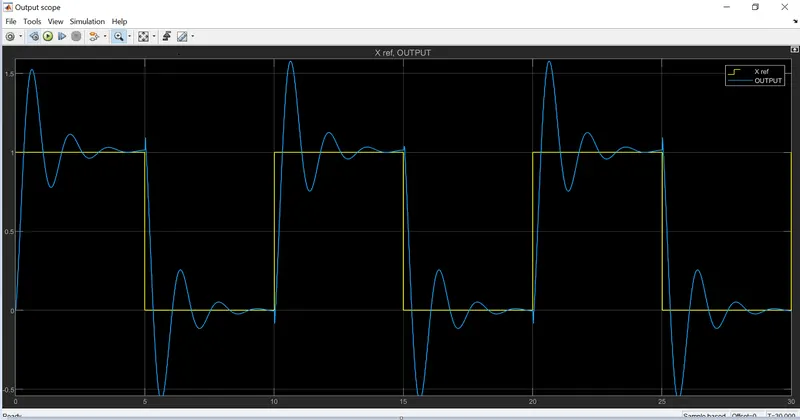
From matlab function Kp Ki and Kd values derived all the values given to the simulink function blocks to derive the output.All output were shown in the Result.
PID output analysis picture
Result
To complte the project of Position control of mass spring damper system transfer function of a mass spring damper system and use it in the model. Add a PID controller to adjust the force on mass so that its position follows a reference signal to using matlab and simulink wave from plot.
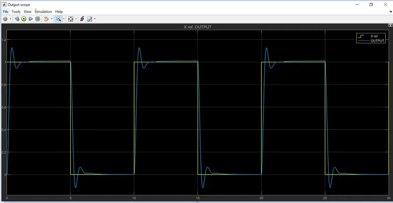
Output 1- Value derive from function
Output 2 PID varrying
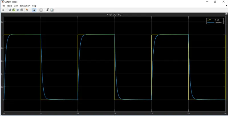
Output 3 PID varrying