Project 2 - Modeling of 3 phase Induction Motor Drive
AIM:
1.Model 3 Phase Inverter using Simulink (model the parasitic as well) with a switching frequency of 10Khz using 3 phase Squirrel Cage Induction motor, using V/F method, open loop
Design Parameters:
Power = 100 HP
DC Voltage = 800 V
Output Voltage = 460 VRMS – line to line
Initial Speed = 1500 RPM
Final Speed = 1000 RPM
Initial Load Torque = 10 Nm
Final Torque=20 Nm
Torque Step Time = 0.1 secs
2.Use the 3 phase inductor motor theory to derive the transfer function of 3 phase Induction Motor
3.Model 3 phase induction motor with a 3 phase inverter using Direct Torque control using an Average Model, Implement both torque and flux control to achieve desired power.
Design Parameters:
Initial Speed = 0 RPM
Flux Target = 2.5 webers
DC Voltage = 500 V;
Fundamental Frequency = 60 Hz
Speed Step Time = 0.01 secs
Determine fundamental speed based upon fundamental frequency
Determine the switching sequence for direct torque control
Moment of Inertia = 0.1 Kgm^2
Load Torque Initial = 0 Nm
Final Load Torque = 50 Nm
Torque Step Time = 0.03 secs
Motor Parameters: (Create an Average Model)
Stator Resistance = 0.5 Ohms
Rotor Resistance = 0.2 Ohms
Stator Leakage Inductance = 20 mH
Rotor Leakage Inductance = 10 mH
Magnetizing Inductance = 200 mH
Number of Poles = 4
Torque to Speed
REPORT:
1.THREE PHASE INDUCTION MOTOR SIMULATION
MOTOR DETAIL - Induction Motor model – use Asynchronous Machine from Simulink with Squirrel Cage Preset Model – 05 , for 100HP Motor
POWER = 100 HP
VOLTAHE = 480V
FREQUENCY = 60HZ
SPEED = 1780RPM
Calculation:
Torque = ((100/746)*60)/(2/3.14/1780)
Torque = 400Nm
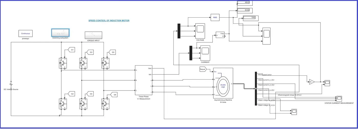
Speed control of V/F mode.
Inverter generate the 1/8 ratio to generate the at every one frequency generate 8 volt
(ie)
| HZ | Volt |
| 1 | 8 |
| 2 | 16 |
| 10 | 80 |
| 25 | 200 |
| 30 | 240 |
| 50 | 400 |
| 60 | 480 |
SPEED CONTROL FUNCTION:
Speed of the induction motor directly propotional applied voltage and its frequency
Frequency and voltage is maintainimg the ratio to maintain the rotor fulx constant.
The open loop V/F control of an induction motor is the most common method of speed control because of its simplicity and these types of motors are widely used in industry. Traditionally, induction motors have been used with open loop 50Hz power supplies for constant speed applications. For adjustable speed drive applications, frequency control is natural. However, voltage is required to be proportional to frequency.Remains constant if the stator resistance is neglected. The power circuit consists of a diode rectifier with a single or three-phase ac supply, filter, and PWM voltage-fed inverter. Ideally, no feedback signals are required for this control scheme.
The PWM converter is merged with the inverter block. Some problems encountered in the operation of this open loop drive are the following:
The speed of the motor cannot be controlled precisely, because the rotor speed will be slightly less than the synchronous speed, and in this scheme, the stator frequency and hence the synchronous speed is the only control variable.
The slip speed, being the difference between the synchronous speed and the electrical rotor speed, cannot be maintained, as the rotor speed is not measured in this scheme. This can lead to operation in the unstable region of the torque-speed characteristics.
SIMULATION:
Simulation first torque 10Nm 2.5% of rated load and after 0.1s torque reached to 20Nm 5% of rated load.TSimulation torque very very low.So torque is heavily oscillating
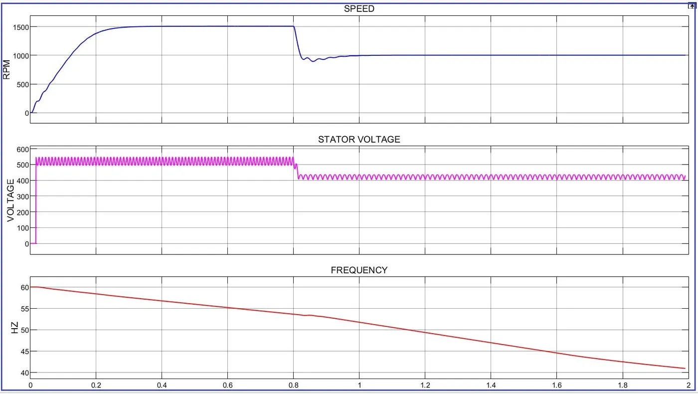
0.2S Motor reached 80% of rated speed.After 1 sec motor reached 1500rpm.
V/F SIMULATION:
SIMULATION MODEL:
STATOT VOLTAGE,SPEED AND FREQUENCY PLOT:
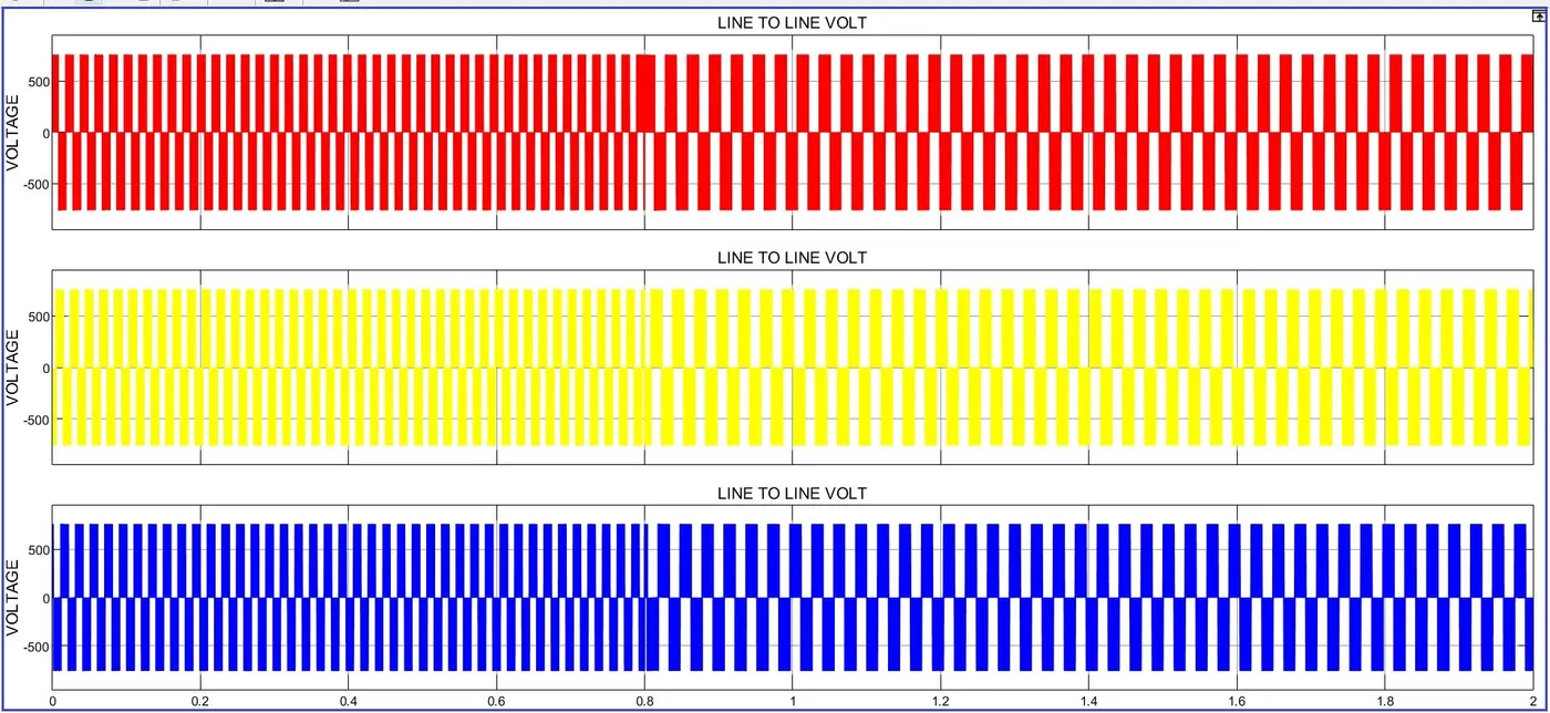
LINE VOLTAGE:
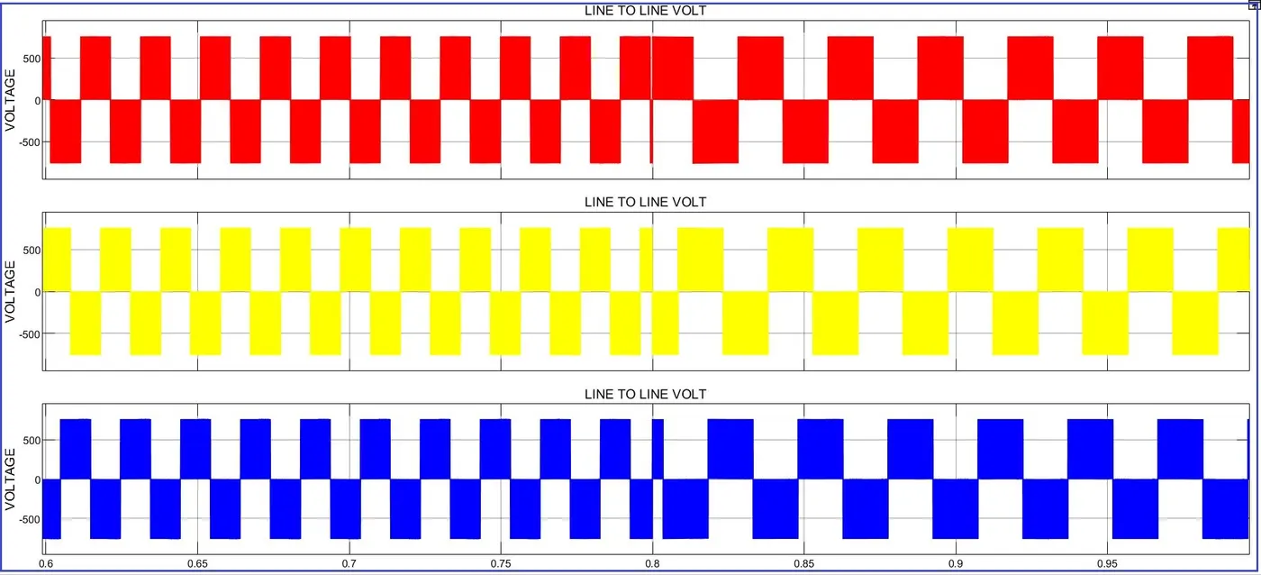
VOLTAGE ZOOM:
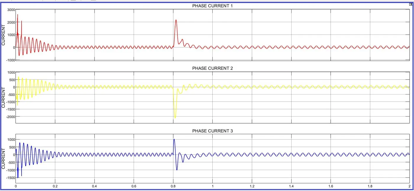
LINE CURRENT:
TORQUE SETPOINT:
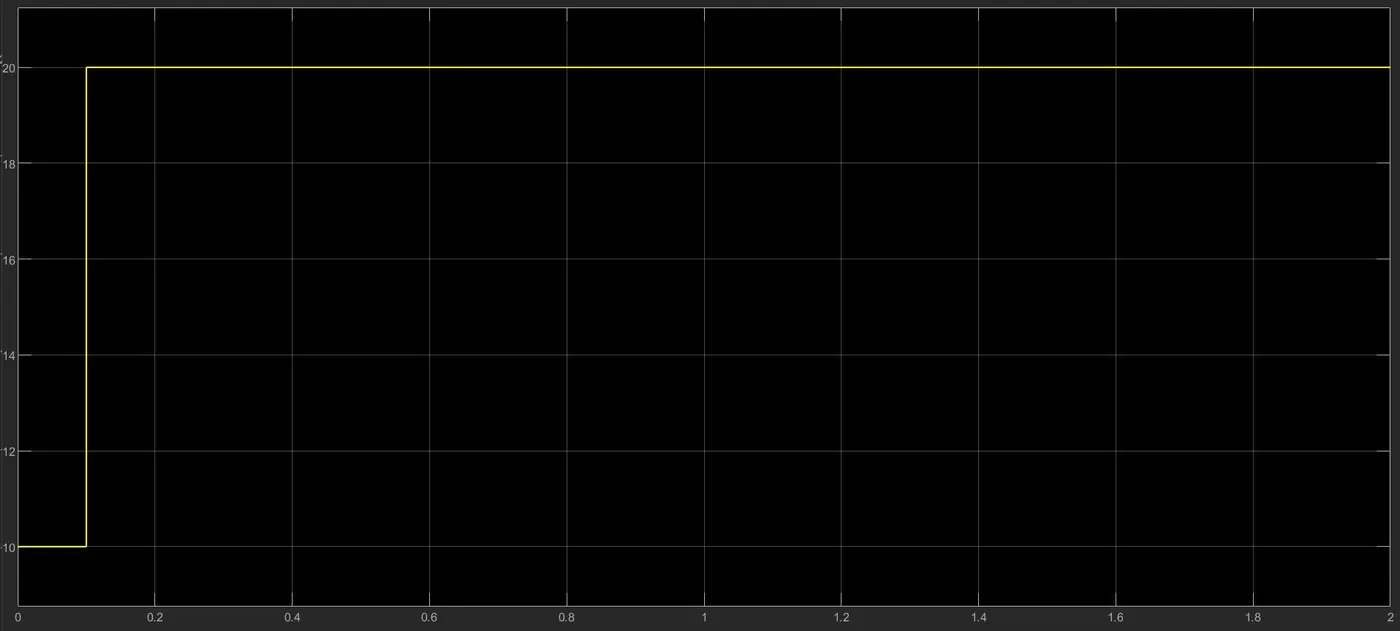
ACTUAL TORQUE:
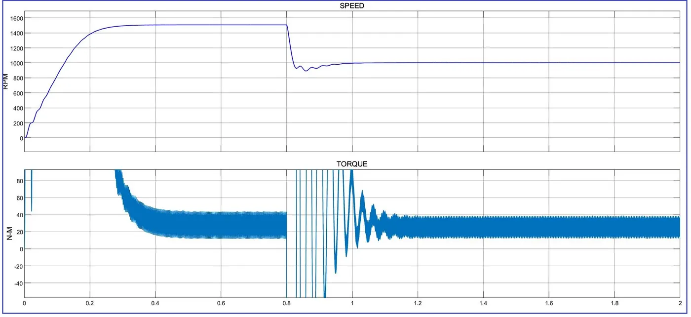
SIMULATION RESULT:
1.Initial load torque set 10nm after 0.1 sec it reached 20nm.No variation appeared in the speed and current.
2.Initail speed 1500rpm.Motor speed slowly raised and reached 0.3.After 1 seconds speed reduce to 1000rpm.It working good.
3.All sheets attached.
2.Transfer function of induction motor
The transfer function of an Induction motor is obtained from the Mathematical modeling of an induction motor and by taking all the required basic Equations.
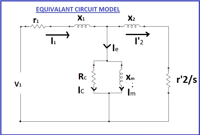
r1=resistance of Stator
X1=Stator leakage reactance
I1=stator current
Rc=shunt branch resistance
Xm=magnetizing reactance
Ie=per phase no-load current
I2=Rotor current
I2'=Rotor Current per phase referred to as stator
X2'=standstill rotor reactance referred to as stator
r2'=rotor resistance referred to as stator
V1=Stator Voltage
E1=stator induced emf
s=slip
The electrical equation of the machine is
Va=Ia*Ra+JXs*Ia+Eb
where Eb ∝ (dθ/dt)
Applying Laplace transforms,
Va (s) = Ia(s) (Ra + jXs) + Eb(s)
we know that
Eb = Kt sθ(s)
substituting, we get
Va(s)=Ia (s) Z(s) + Kt s θ(s)
Va (s)−Kt (s) sθ(s) / Z(s) = Ia(s)
Electrical Torque is given by
Te=E2sinθ
Mechanical Torque is given by
Tm=Jθ + Bθ
Taking Laplace Transforms,
Tm (s) = (Js2+Bs) θ(s)
Tm=Te⇒E2 θ(s) = Js2 + Bs(θ(s))
(Js2+Bs−E2) θ(s) = Tm
Js2+Bs−E2=(Tm / θ(s))
θ(s) / Tm (s) =1 / (Js2+ Bs−E2)
we know that T∝ϕIa cosθ (take θ=0)
T = Kϕ Ia
T = Kϕ (s) Ia(s)
From the above we know
Ka [Va(s)−Kts θ(s)] Z(s)=(Js2+Bs−E2) θ(s)
Ka Va (s) = (Js2+Bs−E2) θ(s) Z(s) + Kts θ(s)
[Va(s) / θ(s)] = (Js2+Bs−E2) Z(s) + Ka Kts Ka
θ(s) / Va(s) = Ka (Js2+Bs−E2) Z(s) + Ka Kts
θ(s) / Va(s) = Ka (Js2+Bs−E2) (Ra + Las) + Ka Kts
The transfer function of the induction motor is given as
θ(s) / Va(s) = Ka / [JLas3 + (Ra J + B La) s2 + (B Ra + Ka Kt) s]
3.Model 3 phase induction motor with a 3 phase inverter using Direct Torque control using an Average Model, Implement both torque and flux control to achieve desired power.
Direct Torque Control (DTC) is an optimised AC drives control principle where inverter switching directly controls the motor variables flux and torque.
The measured input values to the DTC control are motor current and voltage. The voltage is defined from the DC-bus voltage and inverter switch positions.
The voltage and current signals are inputs to an accurate motor model which produces an exact actual value of stator flux and torque every 25 microseconds.
Motor torque and flux two-level comparators compare the actual values to the reference values produced by torque and flux reference controllers.
The outputs from these two-level controllers are updated every 25 microseconds and they indicate whether the torque or flux has to be varied.
Depending on the outputs from the two-level controllers, the switching logic directly determines the optimum inverter switch positions.
DTC:
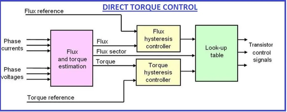
The properties of DTC can be characterized as follows:
- Torque and flux can be changed very fast by changing the references
- High efficiency & low losses - switching losses [de] are minimized because the transistors are switched only when it is needed to keep torque and flux within their hysteresis bands
- The step response has no overshoot
- No dynamic coordinate transforms are needed, all calculations are done in stationary coordinate system
- No separate modulator is needed, the hysteresis control defines the switch control signals directly
- There are no PI current controllers. Thus no tuning of the control is required
- The switching frequency of the transistors is not constant. However, by controlling the width of the tolerance bands the average switching frequency can be kept roughly at its reference value. This also keeps the current and torque ripple small. Thus the torque and current ripple are of the same magnitude as with vector controlled drives with the same switching frequency.
Simulation:
In this simulation space vector modulation method is used to the DTC algorithum.
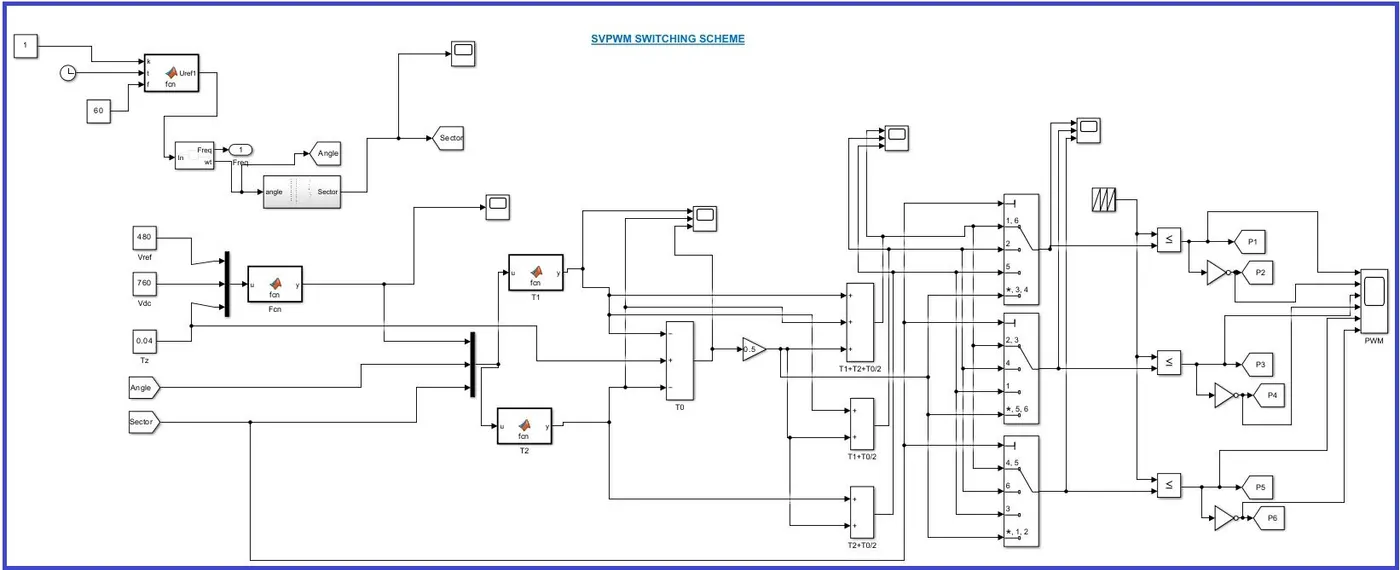
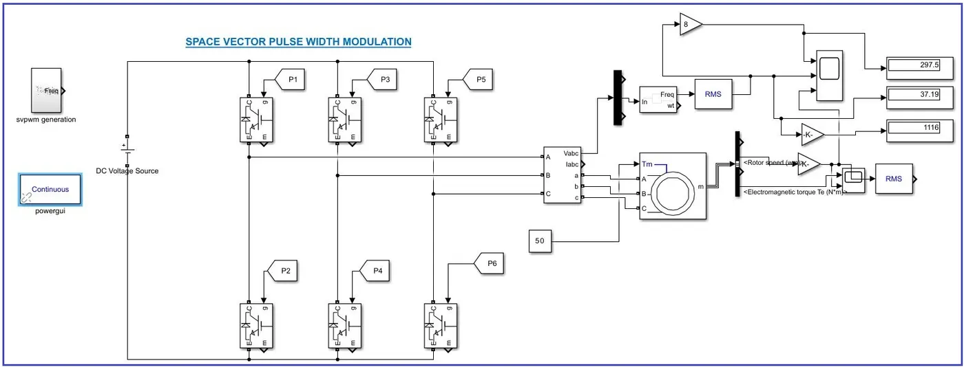
Simulation Result: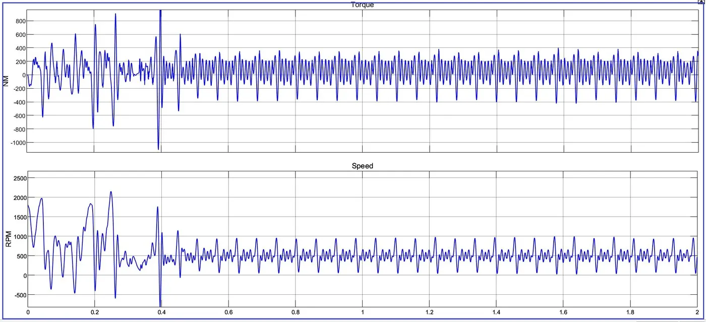
Simulation Result:
Huge variation in the torque