Project - Position control of mass spring damper system
Q.1 - Obtain the transfer function of a mass spring damper system and use it in the model. Add a PID controller to adjust the force on mass so that its position follows a reference signal.
Take m = 3.6; %kg k = 400; %N/m c = 100; %Ns/m
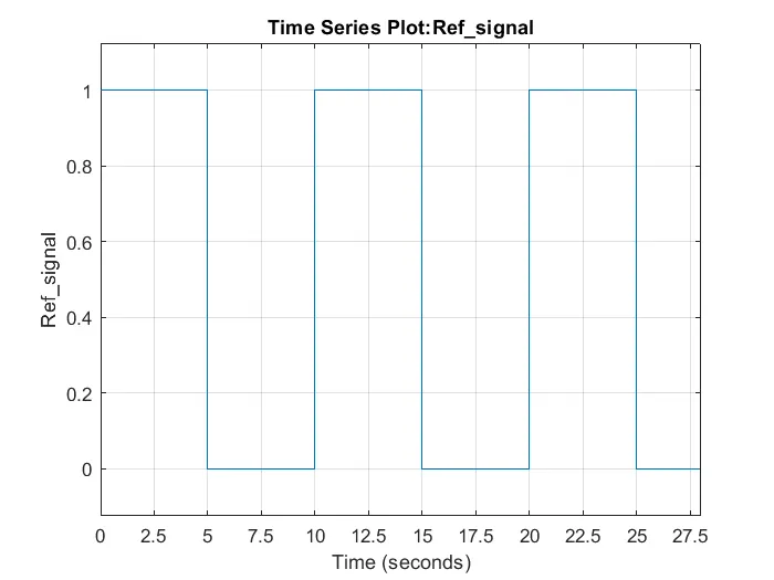
The reference signal is shown in the following figure.
Sol-
Parameters used for position control of spring mass damper system
% Initial conditions
m = 3.6; % kg
k = 400; % N/m
c = 100; % Ns/m
% A and B matrices
A = [0 1; -k/m -c/m];
B = [0; 1/m];
% Placement of poles
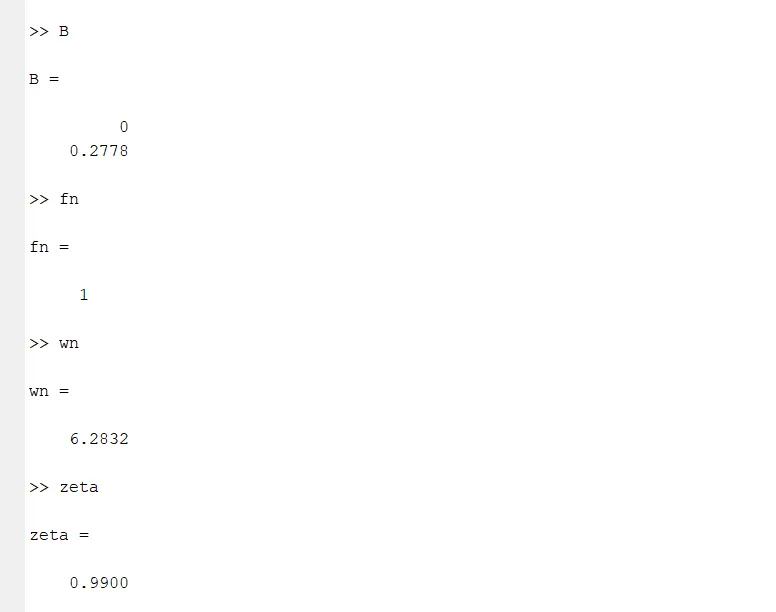
fn = 1.0; % 1Hz natural frequency design
wn = 2*pi*fn; % Natural frequency in rad/s
% zeta = 1.0; % for a critical damped design
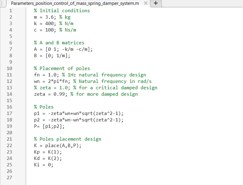
zeta = 0.99; % for more damped design
% Poles
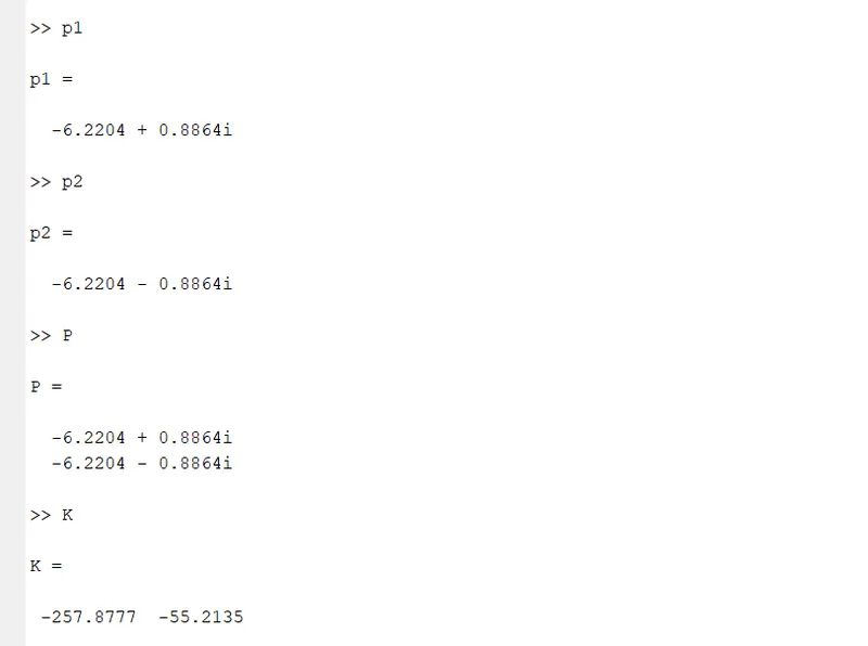
p1 = -zeta*wn+wn*sqrt(zeta^2-1);
p2 = -zeta*wn-wn*sqrt(zeta^2-1);
P= [p1;p2];
% Poles placement design
K = place(A,B,P);
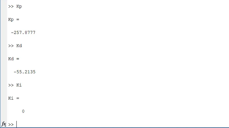
Kp = K(1);
Kd = K(2);
Ki = 0;
zeta = 1.0 % for an critical damped design
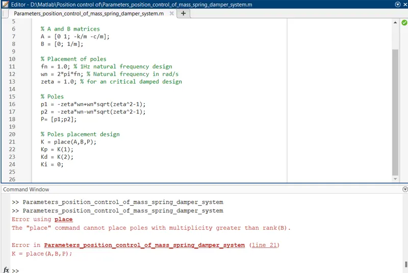
Both poles p1 and p2 are same -6.2832
when both poles are the place command cannot place poles multiplicity greater than rank(B)
Now, taking zeta = 0.99
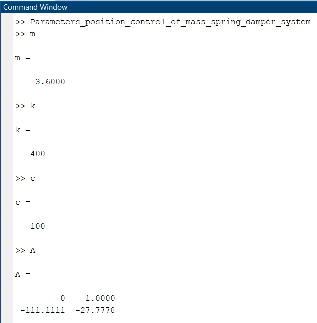
Command window:
Simulation:
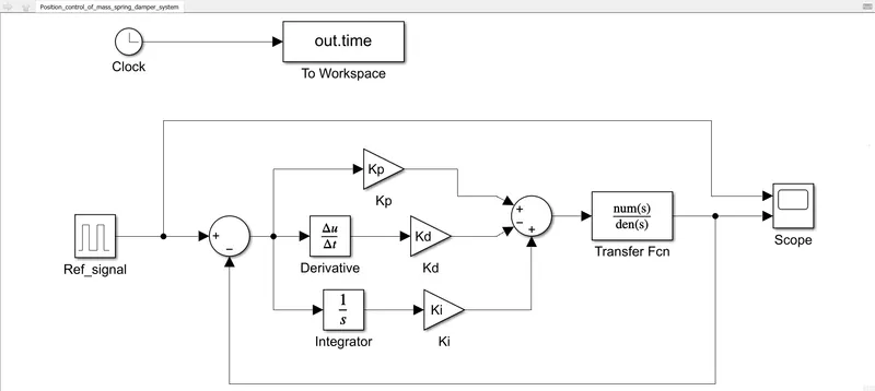
Block used:
Clock
To workspace
Pulse Generator (Ref_signal)
Sum block
Gain block
Derivative
Integrator
Transfer function block
Scope
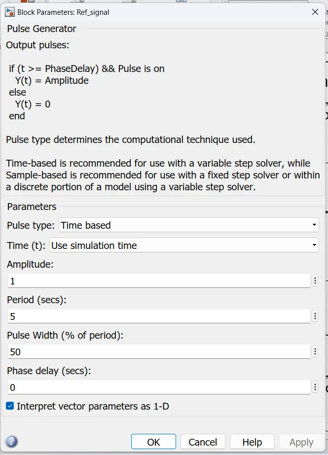
As a reference signal using a pulse generator with PID design, we are using it to control the position of the spring mass damper system.
Pulse Generator parameters using as given:
Transfer Function Parameters
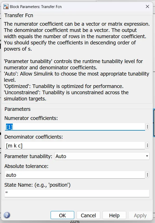
Num = 1
Den = [m k c]
num(s)/den(s) = 1/(m * s ^ 2 + c * s + k)
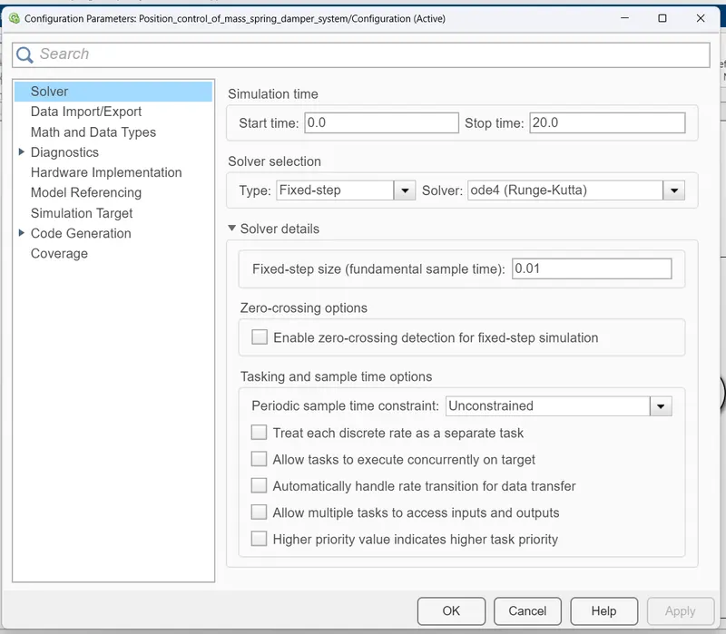
Model Settings Parameters
Scope:
Kp = -257.8777
Kd = -55.2135
Ki = 0
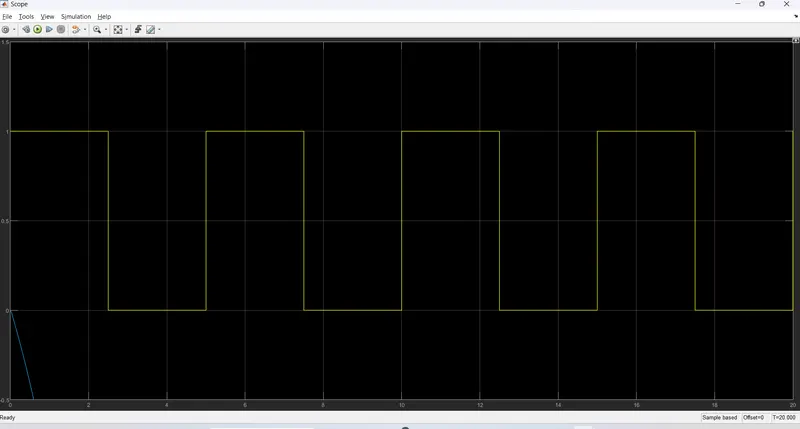
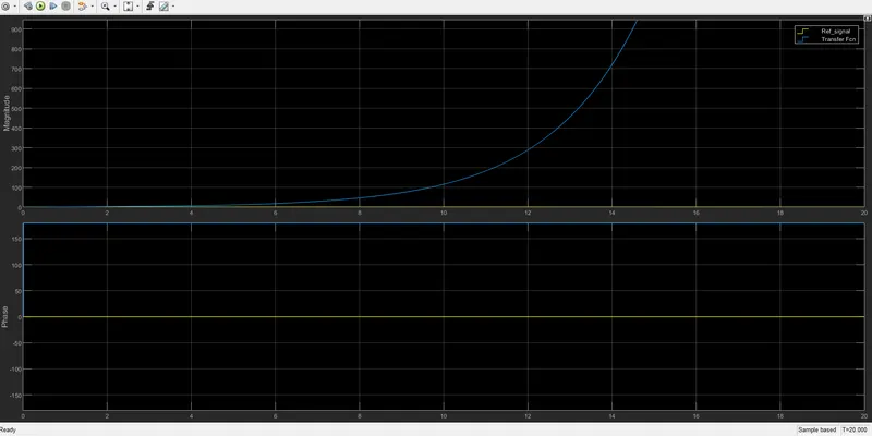
there is an error between the reference signal and the simulated signal when ki = 0
Kp = -257.8777
Kd = -55.2135
Ki = 1000
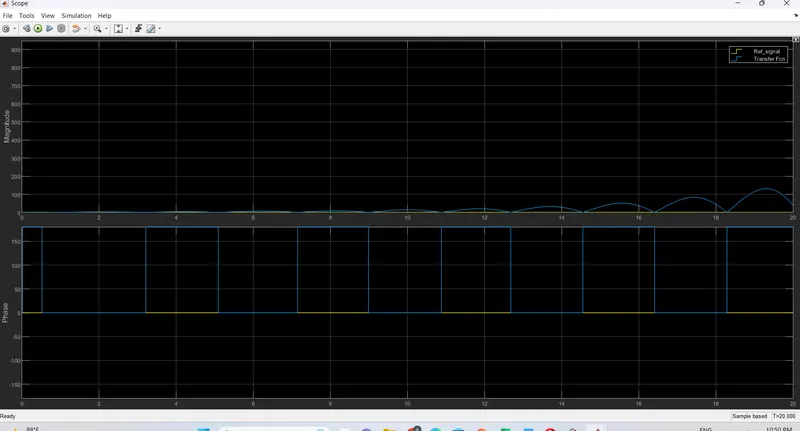
Kp = -257.8777
Kd = -55.2135
Ki = 5000
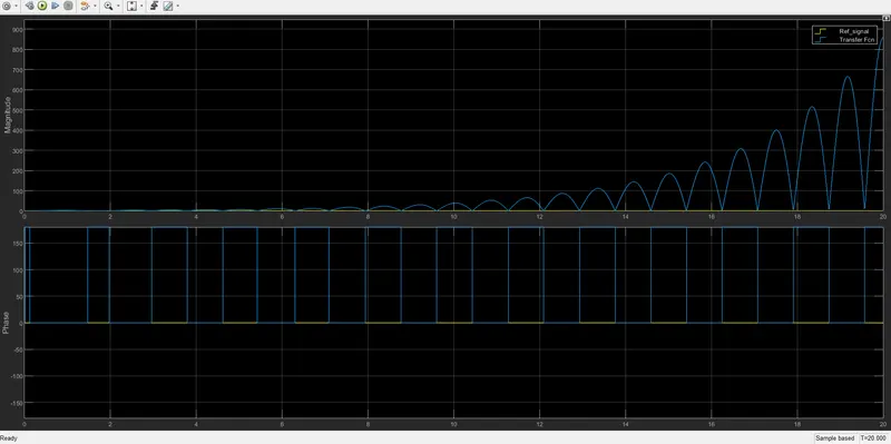
Ki value changes the position of the spring-mass damper system.
ki = 5000, the graph more accurate and stable system.