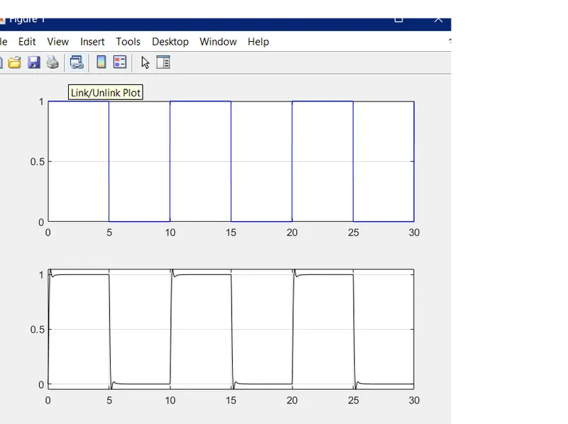
Project - Position control of mass spring damper system
1.
The transfer function of a mass-spring-damper system can be obtained by applying Newton's second law of motion to the system. The equation of motion is:
m * x''(t) + c * x'(t) + k * x(t) = f(t)
Where:
- m is the mass of the system
- c is the damping coefficient
- k is the spring constant
- x(t) is the displacement of the mass from its equilibrium position at time t
- f(t) is the external force applied to the system at time t
Taking the Laplace transform of the equation, we get:
m * s^2 * X(s) + c * s * X(s) + k * X(s) = F(s)
Where X(s) and F(s) are the Laplace transforms of x(t) and f(t) respectively. Solving for X(s), we get:
X(s) = F(s) / (m * s^2 + c * s + k)
This is the transfer function of the mass-spring-damper system.
In Matlab
close all
clear all
clc
% Given parameters
m = 3.6; % kg
k = 400; % N/m
c = 100; % Ns/m
% Calculate natural frequency and damping ratio
wn = sqrt(k/m);
zeta = .7; % desired damping ratio
% State-space model
A = [0 1; -k/m -c/m];
B = [0; 1/m];
C = [1 0; 0 1];
D = [0; 0];
sys = ss(A, B, C, D);
% Jacobian matrix
J = [A(2,1) A(2,2) B(2)];
% PID gains
kp = (2*zeta*wn*m - c)*J(1) + (wn^2*m - k)*J(3)
kd = (2*zeta*wn*m - c)*J(2) + (wn^2*m - k)*J(3)
ki = 0
In Simulink
clock block and to worksace block is used and then Pulse generator is used to generate the given signal
Pulse generator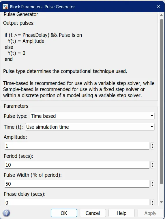
Given Signal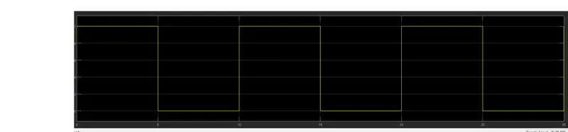
After that a sum block is used to substract the feed back signal and then a PID model is made using Integrator block gain block as shown in the figure
PID controller
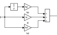
After that transfer function block is used and an refrence signal is provided to the sum block and then to workspace block is used to get the output