Project - Position control of mass spring damper system
Transfer function of mass spring damper system
Differential equation representing the mass spring damper system
f(t) = m*xdotdot + c*xdot +k*x
OR
f(t) = m*d^2x/dt^2 + c*dx/dt + k*x
Apply laplace transform to the above differential equation
F(s) = m*s^2*x(s) + c*s*x(s) + k*x(s)
OR
F(s) = (m*s^2 + c*s + k) x(s)
In Transfer function
X(s)/F(s) = 1/(m*s^2+c*s+k) = K/(s^2+2*zeta*wn+wn^2) = 400/(s^2 + 2*zeta*wn + wn^2)
Given values are
m= 3.6 kg;
k= 400 N/m;
c= 100 Ns/m;
A matrix =[0 1; -k/m -c/m]; B marix=[0 1/m];
Calcualtion of wn
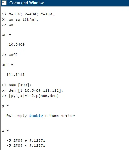
Matlab script for finding Kd and Kp values using place command
% This file contains design parameters
m=3.6;
k=400;
c=100;
wn=sqrt(k/m);
wn=10.5409;
%% Design of PID controller
A(1,1)=0;
A(1,2)=1;
A(2,1)=-111.11;
A(2,2)= -27.777;
B(1)= 0;
B(2)=0.2777;
%%% Pole placement
zeta=0.5;
wn=10.5409;
p1=-zeta*wn+wn*sqrt(zeta^2-1);
p2=-zeta*wn-wn*sqrt(zeta^2-1);
P=[p1;p2];
K=place(A,B,P)
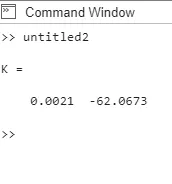
Command window for Kp and Kd values
Simulink model
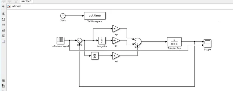
a) Reference signal is given in the question as pulse signal. We are suppose to take this signal as reference signal only.
b) We are using two sum blocks ( sum and sum1 block), one integrator block, one derivative block, three gain blocks (Kp,Ki,Kd) and one transfer function block( 1/(m*s^2+c*s+k)).
c) output of refernce signalis connected to positive of sum block, output of sum block is connected to integrator , and also output of sum is connected to derivative block , Kp gain block is also connected to the output block of sum.
d) output of intehrator is connected to Ki gain block, output of Kp is connected to positive of sum1 block, Ki is connected to second positive of sum1 block, Kd is connected to third positive of sum1 block.
e) output of derivative block is connected to kd.
f) Output of sum1 block is connected to the transfer function block, and its output is connected to negative of sum block.
g) Scope is connected to the output of transfer function to view a desired output.
h) Kp value is 0.0021 and Kd value is -62.0673 are calculated in matlab using place command and Ki is tuned
manually.
Output response for ki = 500
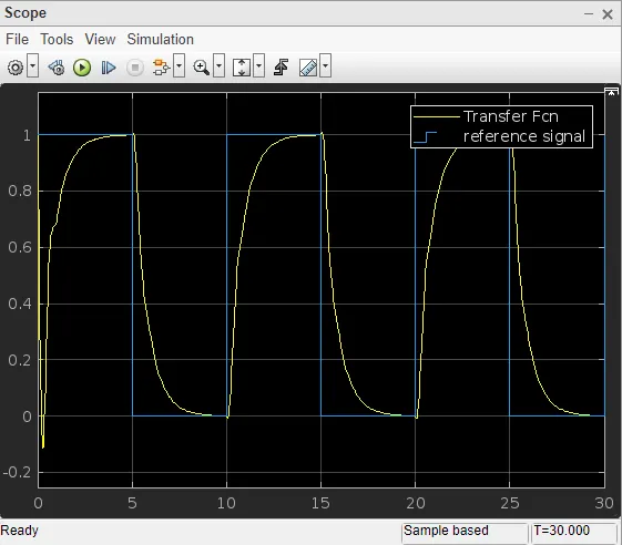
Explanation of the responses is given below in the last
Output response for lower value Ki = 50
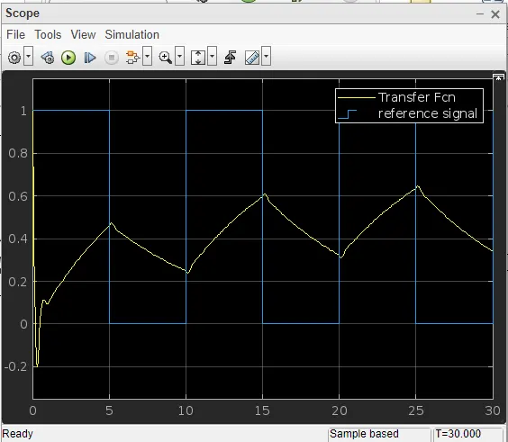
Output response for lower value Ki = 100
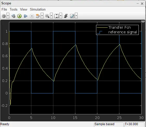
Output response for lower value Ki = 300
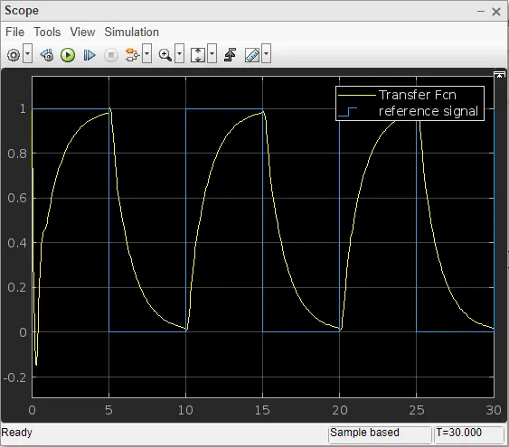
From the above waveforms it is clear that lower the value of Ki, the output response do not follow the reference signal given.
Higher the value of Ki which is Ki = 500, the output response follows the reference signal given in the above first waveform, but not exactly , we can a see slight changes in the transfer function response as comapared to the reference signal.
If we are using the lower Ki value, we cannot see slight changes in a transfer function waveform as comapared to the reference signal.
So, it is clear that we are suppose to tune higher Ki value comapred to the Kp and Kd values to view desired response of transfer function which follows the reference signal.