Project - Analysis of a practical automotive wiring circuit
Answers
1) The major elements in the automotive wiring diagram are :-
- Battery
- Starter
- Ignition Switch
- Fuse box
- Generator(Alternator)
- Current and Voltage regulator
- Distributor
- Spark Plug(s)
- Ignition Coil
- Breaker
- Various Lights and their switches
2) The purpose and working of any three elements :-
1. Ignition Coil
An ignition coil is used to transform the battery voltage to a much higher voltage required by the spark plug(s). The ignition coil is used in the ignition system of spark-ignition engine. The spark plug(s) then use this burst of high-voltage electricity to ignite the air-fuel mixture.
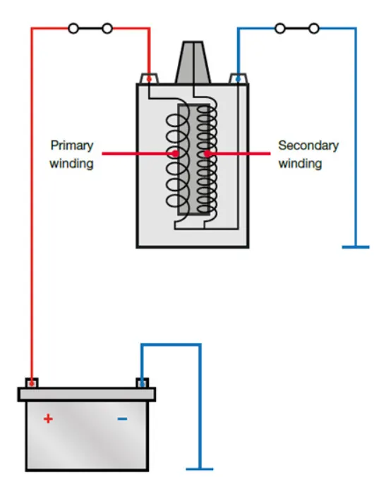
An ignition coil consists of an iron core surrounded by two windings made from copper wire. The primary wire has heavy wire with relatively less number of turns and the secondary wire is smaller wire that consists of thousands of turns. The wires are insulated from from the high voltage by enamel and layers of oiled paper insulation.
When the coil is connected to the battery, current flows through the primary winding, which produces a magnetic field around the core. This current lasts for a period of time to build up energy in the coil until the circuit is opened by the breaker. Once the coil is charged, the circuit is opened, and the resulting oscillation in the magnetic field induces a high voltage in the secondary winding. This high-voltage electricity travels through several components, befroe reaching the spark plug(s).
2. Alternator
Alternator is a device which distributes electricity to the car, when the engine is on and recharges the battery.
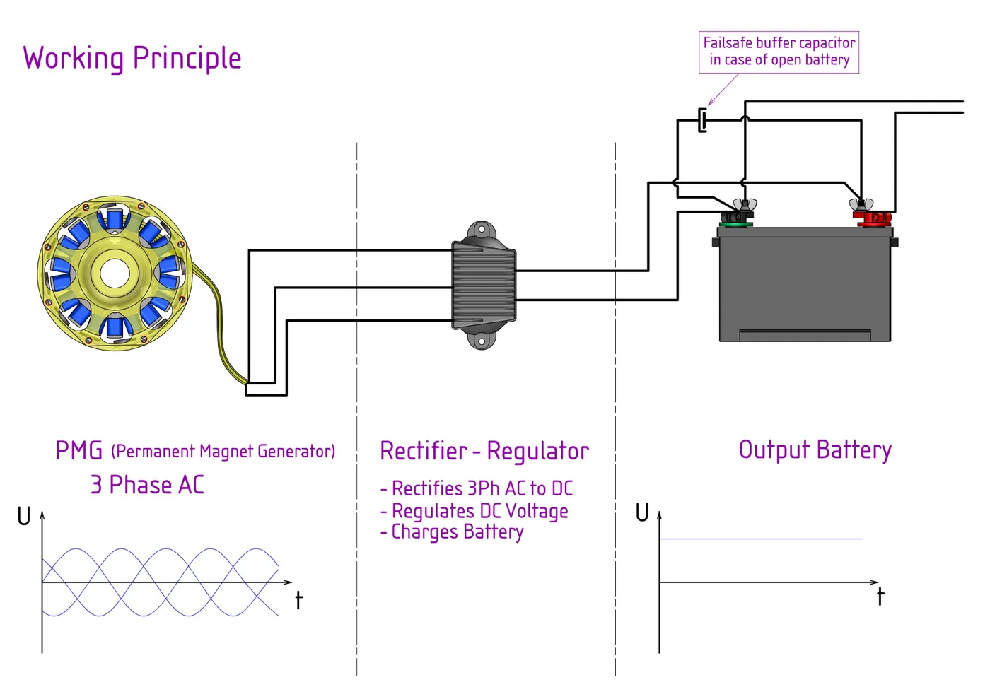
The rotor and stator are the electricity-producing components of an alternator. The rotor, a cylindrical piece surrounded by magnets, spins inside of the stator, which holds a fixed set of conductive copper wiring. The movement of the magnets over the wiring is what ultimately creates electricity. The stator is attached to the alternator’s shell and does not move. It consists of the outer frame, stator core and stator winding. The stator, unlike the rotor, is highly insulated due to the high voltage that it creates.
Electrical energy is made as the rotor spins. The magnets surrounding the rotor are deliberately placed so that as they pass over the copper wiring in the stator, a magnetic field is created. This magnetic field, in turn, produces voltage that is captured by the stator. This power then reaches the voltage regulator, which disperses electricity to the vehicle and manages the amount of voltage the battery receives.
3. Current and Voltage regulator
A voltage regulator is a circuit that creates and maintains a fixed output voltage, irrespective of changes to the input voltage or load conditions. This is important as fluctuations in voltage can damage the circuit in an automobile and may cause fire too.Current regulator is a device that provides a constant current regardless of change in load or supply. Current regualtors are designed to control and stabilize the flow of electric current in motor circuits, ensuring optimal and safe performance.
The motor current regulator operates based on the principle of Ohm’s law, which states that the current passing through a conductor between two points is directly proportional to the voltage across the two points. Motor current regulators ensure that the current flowing through the motor remains within the permissible range, protecting the motor from damage due to overcurrent conditions.
3) If the current in the circuit is 10A, then the ideal fuse rating should be 120% to 130% of the current.
That translates to fuse of 12A to 13A. But when we search in market, we would probably get 15 A, and hence the fuse raring should be 15A.
4) Given, 500 W is the load,
taking battery voltage = 12v,
Current at full load = 500/12 = 41.67 A
Let us assume that the battery powers the system at full load for 1.5 hours.
Hence required battery capacity = 41.67 x 1.5 = 62.505 Ah
hence, we should get battery with 60 Ah capacity.
5) There many components in the system that are connected in parallel, such as sealed beam(s), parking lights, horn(s), tail lights ,etc.
This is because each of the components required a voltage of 12v from the battery, which the parallel connection provides. If these are connected in series, then there would be voltage drop across each component and hence all components would not get enough voltage for their proper functioning.
6) The horn(s) and their switch are connected in series. This is because, horn should only function when the driver wants to use it. The switch closes and opens the path of current to the horn(s) when, toggled on or off. If these two are not connected in series and connected in parallel, there would be no way turn the horn(s) off.