Project - Analysis of a practical automotive wiring circuit
Ans1:
Major elements in the above automotive wiring diagram are as following
- Fuse
- Ammeter
- Ignition Switch
- Battery
- Starter
- Ignition coil
- Distributor
- Generator
- Current and voltage regulator
- Breaker
Ans2:
Purpose and working of any three of the above elements briefly
1.Ignition coil
Ignition coil is used to produce the spark inside the cylinder engine and this ignition can only happen either by compression or spark. In case of a gasoline engine the ignition is created by the spark and to create this spark a very high voltage is needed ( in the order of thousands ~40,000). To produce this high voltage from a low voltage source (battery 12V) this ignition coil is used.
This coil contains two windings one with lower turn and the other with high number of turns similiar to a transformer wounded on an iron core.
2. Distributor
A distributor is an electro-mechanical device used in the ignition system of a vehicle. The distributor's main function is to route electricity at high voltage from the ignition system to each spark plug at the correct time and correct order of ignition.
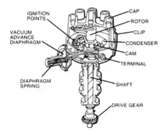
Different parts of an Ignition system
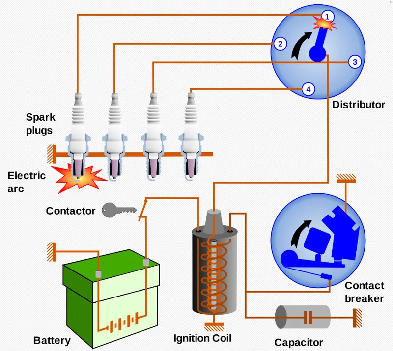
Distributor in the Ignition system
3.Current and voltage regulator
The function of the regulator is to act as a protective device against the fluctuation either in current or in voltage.
Alternator generates voltage based on the input speed if the speed is high voltage generated will also be high and vice versa. So the generated voltage lies in a range. To stablize the these voltage in a specific range (13.8 – 14.8 Volt ) this regulator is used and it is achieved by regulating the amount of the current flowing to the rotor coil by controlling the strength of the magnetic field on the rotor coil.
By ohm's law current flowing through a conductor is directly proportional to the potential difference across it. so when the speed is high voltage generated will also be high and vice versa. So to control the voltage current is controlled and this is achieved by changing the resistance.
Alternator Voltage Regulator for FIAT Ducato III Van
Ans3:
Current drawn from battery = 10A
We have to determine the fuse rating for the given load current and no voltage has been provided for the load so taking the voltage as 12V (as most vehicle has this rating),
ideally,
Fuse rating = power / voltage = (VxI) / V'
Let's say the load also has a potential difference (V') of 12V then
Fuse Rating = (12x10)/12 = 10A
Ans4:
Load (P)= 500W
we have to find out the voltage and capacity of battery
since the duration of load (backup time) is not given so let's take it to be 3 hrs
assume that the current drawn (I) by load is 15A
so
Voltage across the Load (V) = Load / Current drawn = P/I = 500/15 = 33.34V
Hence capacity of battery = Backup time X current rating = 15x3 = 45Ah
Ans5:
Elements that are connected in parallel have the same voltage so elements that are connected in parallel are
- Beam Light
- Horn
These elements are connected in parallel so that the current in the components remains the same. Higher the voltage higher the current will be and this will burn out the equipments.
Ans6:
Elements that are connected in series have the same current so elements that are connected in are
- Ammeter
- Switches
These elements are connected in series so that there is negligible (almost zero) potential drop across these devices. If there is a large potential drop across the terminal of these devices they will short circuit which we don't want.
In other words devices that need to have a very low resistance are connected in series.