Project
Introduction
The Continuously Variable Transmission is a transmission system which regulates the speed according to the ratio of the radius of the primary and secondary gear. It is a belt drive system where the gears act as pulleys, keeping the belt in place. If the primary pulley's radius is lesser than the radius of the secondary pulley, it causes an overdrive. If the primary pulley's radius is more than the radius of the secondary pulley it causes a reduction in speed. Anything which determines the ratio of rpm between the engine shaft and the drive shaft, is a gear. Hence a generic engine has been included in the model.
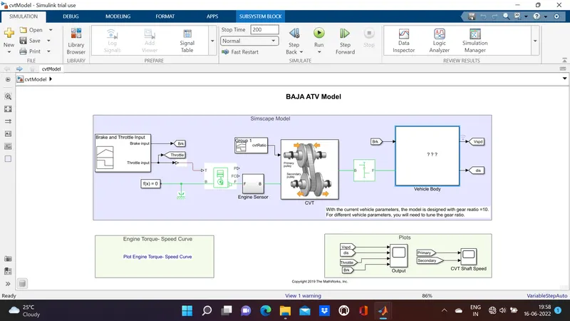
Explanation of the diagram
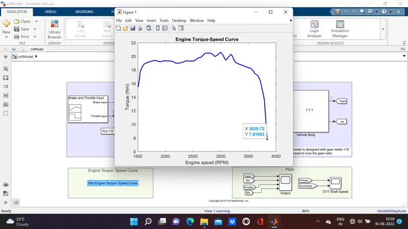
The input signals have been manually fed through a signal builder as the brake input and the throttle input. For the translational motion to act and the braking system to stop the vehicle, the input has been acessed as those two variables only. The Goto function has been used in case the values are needed to be fed into an excel sheet for data points to observe the behaviour of the vehicle at every point in time. A solver configuration is attached with the block to nullify the unkown variables and with the rotational reference. The engine sensor has been used to measure the rpm and accordingly distribute it through the trnasmission to the CVT. The CVT ratio has also been fed as an input to the system as depending on the input, the radius of the pulley will vary. The general relationship between the speed and torque of the vehicle has been obtained. At higher gear ratios, the speed is expected to be higher and torque, less. At lower gear ratios, the torque is expected to be higher and the speed, less.The torque and speed curve as expedited follows the same characteristics, i.e. with increase of speed there is a gradual reduction of torque.
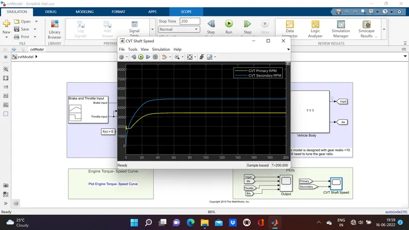
Here, the plot for the primary and secondary RPM of the two pulleys have been obtained. The variation in the graph has occured due to a change in the brake and throttle graph in the signal builder.
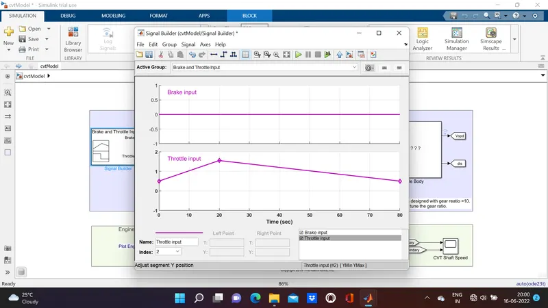
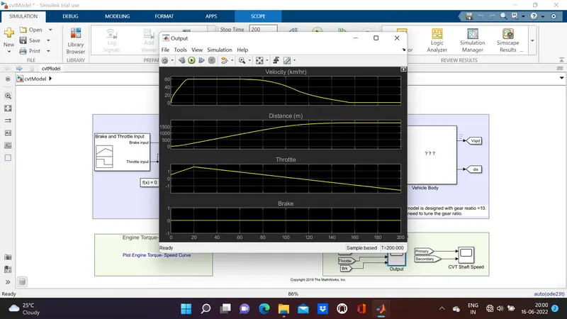
We see that there is a forced change in the throttle at 20s. Keeping the brake input as constant, the difference of the RPM based out of the CVT shows that the vechile has accelerated during the time of the increment in the throttle. This shows that for acceleration, the secondary shaft has to rotate at a higher RPM thant he primary.
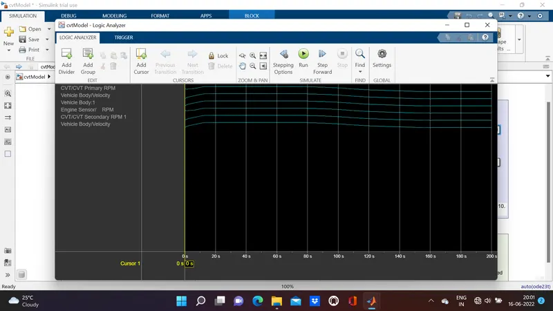
The logic analyser gives a final assessment taking all the parameters into account. This shows a brief comparison in all the factors which influence the running of our model CVT vehicle.
Construction of the sub parts
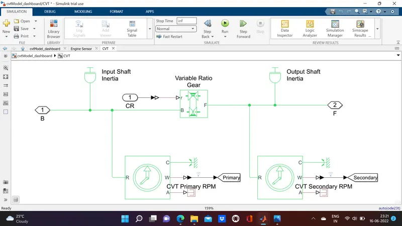
The most important part of the entire model is the CVT which has been designed as above. The motion for the variable gear are attached to different shafts. Hence to give it motion an inertia of motion has been supplied with the help of the block. The primary and secondary pulleys are expected to move at different RPMs. This neccesitates the use of the rotational sensors. The PS termination has been used to ground the unneccessary signals through the angle vector. The angle vector has less relevance with the model.
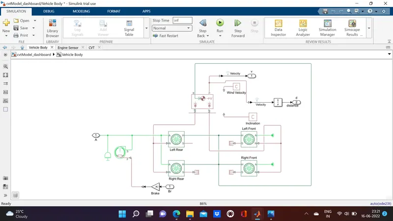
The vehicle body has been culminated into four wheels which give out the translational motion. The input signal initially to the system will be of much relevance here and the output has been provided with a brake shoe to actuate the brakes whenever required. The inclination factor has also been put into account to give the vehicle appropriate elevation whenever required.