Project
Report: All-Terrain vehicle
Aim:
Prepare a technical report of Matlab Simulink simulation of 'All Terrain Vehicle'
Objective:
Run a system-level simulation of an ATV and prepare a report explaining sub-systems of the model along with results.
ATV (All Terrain Vehicle):
An all-terrain vehicle (ATV), as the name implies, it is designed to handle a wider variety of terrain than most other vehicles. It is lso known as a light utility vehicle (LUV). A vehicle that travels on low-pressure or non-pneumatic tires, with a seat that is straddled by the operator, along with handlebars for steering control.
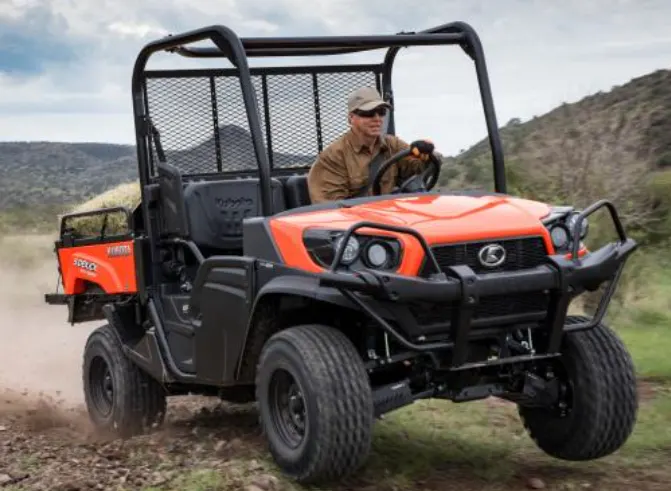
By the current ANSI definition, ATVs are intended for use by a single operator, although some companies have developed ATVs intended for use by the operator and one passenger. These ATVs are referred to as tandem ATVs.
Case Study1:
Simulink model for Baja ATV:
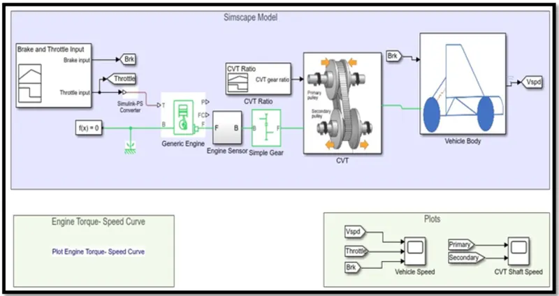
Key components:
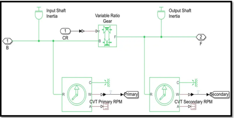
CVT- Continuously Veriable Transmission drive:
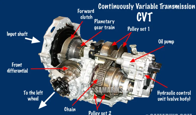
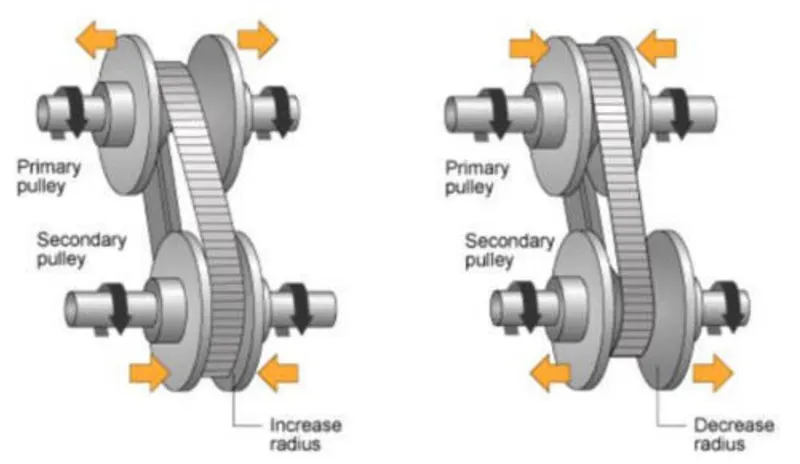
This automatic transmission, instead of an automated gearbox, uses two pulleys of variable diameter connected by a belt. One pulley is turned by the engine, while the other is connected to the differential to run the wheels.CVT uses two pulleys having variable diameters that help the transmission achieve infinite gear ratios. The flow of power from the engine to wheels is continuous and uninterrupted. With no mechanical gears & shafts, the speed transition is smooth while accelerating or de-accelerating.
All of this means an effortless driving experience with a lot of comfort. A CVT has an unlimited number of gear ratios. This means that the engine will always be running at the most efficient RPM, for any given speed. And since the engine is allowed to operate in the highest possible efficiency band, it delivers enhanced fuel efficiency in different driving conditions.
CVT Block:
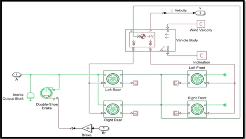
Vehicle Body:
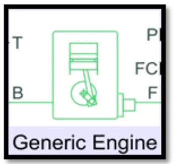
Engine:
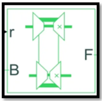
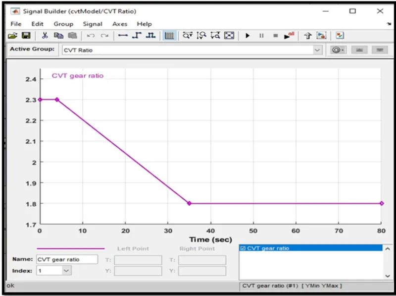
Varable Transmission Ratio:
Input:
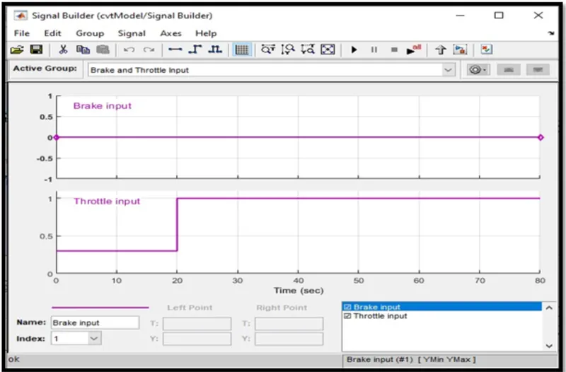
To generate signals for the brake and the throttle, a signal builder is used.
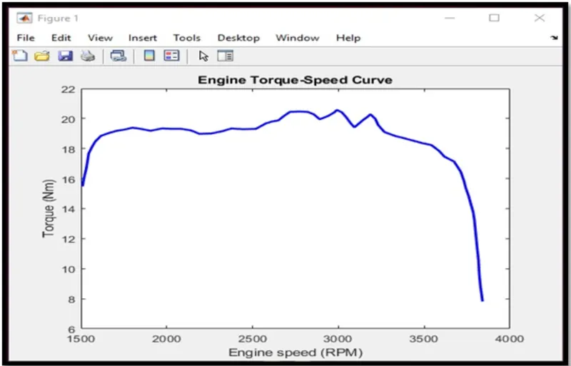
Input- Engine speed vs Torque:
Input-CVT Gear ratio:
Output:
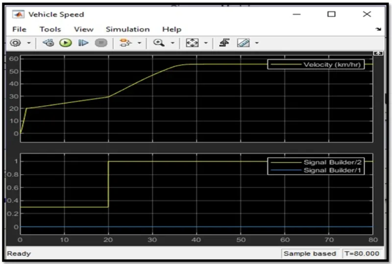
Vehicle speed:
The vehicle attains its max speed at full throttle=1 after 30 sec and then it is constant. the brake inout is 0, so it has zero effect on velocity.
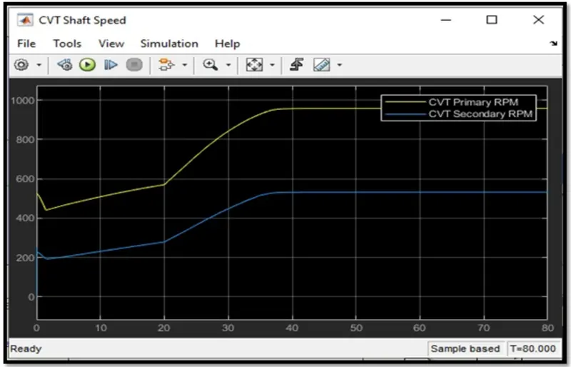
CVT shaft RPM:
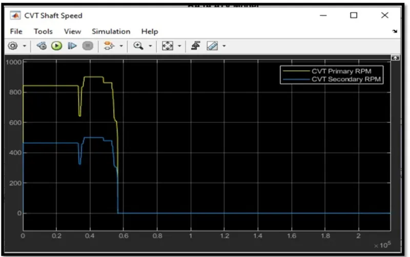
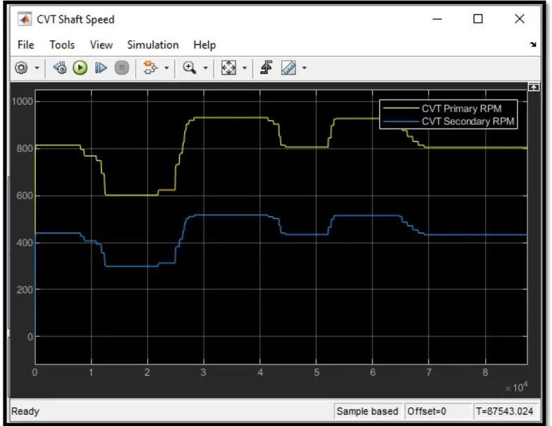
Variation in angular velocities of input and output of the VGT system. these values varies with gear ratio.
Case2:
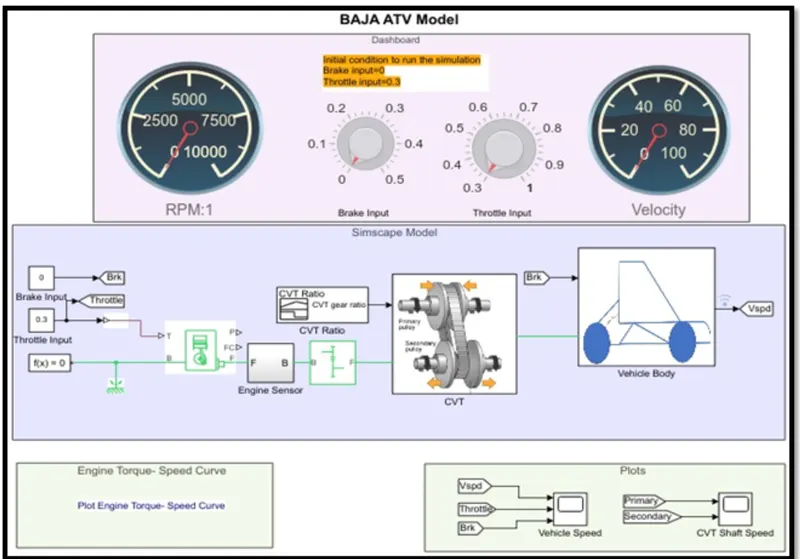
Simulink modeling for BAJA ATV with CVT using dashboard:
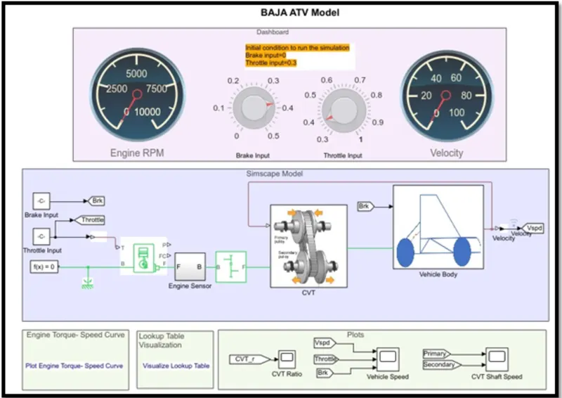
This dashboard conatinas knobs to control the inputs. In this case, Throttle and brake are not provided using signal builder. the knob is given to control both variables in real- time.
Output:
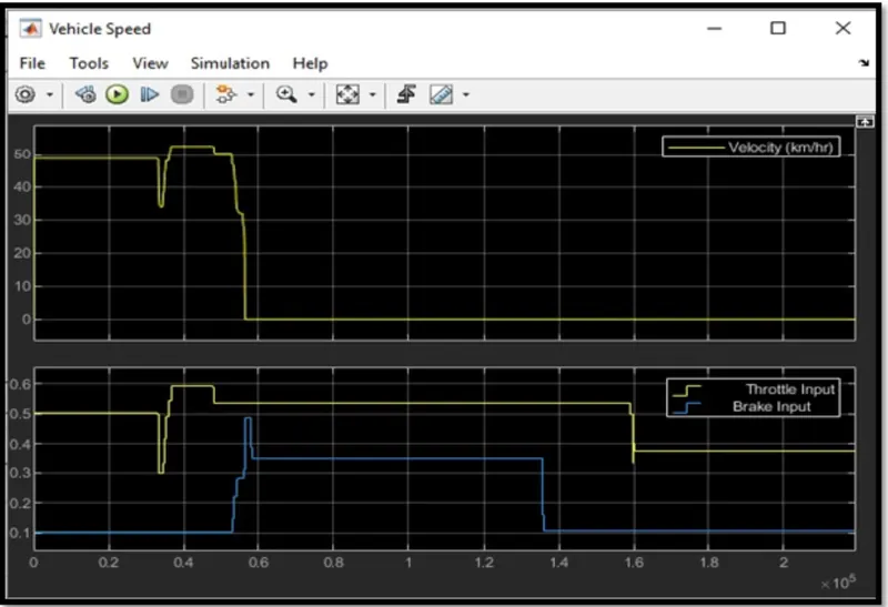
Vehicle speed:
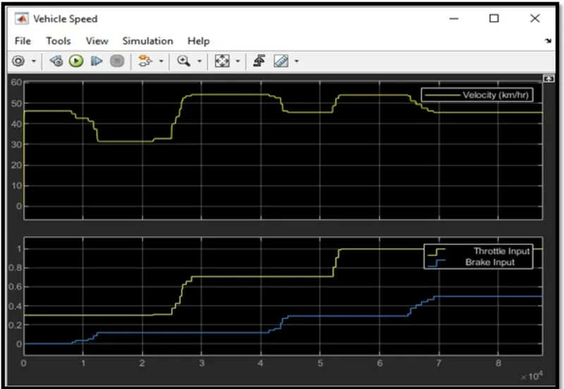
This graph gives direct relation between vehicle velocity wrt throttle and brake. The velocity of the vehicle rises suddenly from 0 to 50km/hr when throttle valie is 0.5 and brke is 0. when brake increases from 0.1 to 0.5; vehicle velocity reduces to 0.
CVT shaft RPM:
Case study 2:
Simulink model using lookup table and dashboard:
To control the inputs- Throttle and Brake with given knobs.
Output:
Vehicle speed: CVT Shaft RPM:
Conclusion of the case study:
With this study we analysed 4 different models and their input/ output.
We compared the trend of vehicle velocity wrt throttle and brake.