Project
EXPLANATION:

components-
1.vehicle body
2.suspension
3.tire
4.engine
5.CVT

 the BAJA ATV Model-

- in this model compnents are CVT,vehicle body,engine  etc,.
- signal builder is giving as input for brake speed 0 and throttle input from 0.3 to 1.
- after certain time throttle is increases and velocity increases and reaches to maximum velocity.

 Generic Engine -

- in generic engine the data for torque and speed are taken from graph and the graph is under model as plot engine torque-speed curve.
- throyyle input is given to the engine as torque as input.
- B connectinon is connected to engine block and it is connected with mechanical rotational reference(MRRef) and Solver configuration.
- F connected for crank shaft to the engine sensor to know the R.P.M and a sensor is attached to know about it.
-

 CVT -

- In CVT we give input and output shaft inertia indicates as primary and secondary pulley in CVT.
- variable gear ratio attached to them to know ratio and to know RPM ideal rotational motion sensor 1 and 2 are indicated as CVT Primaryand Secondary RPM attached to them.
- engine sensor is attached and for speed reduction we given simple gear.
- a variable CVT ratio is given to CVT.
- to the CVT a simple gear is attached.

Vehicle Body -

- in vehicle body 2 front and 2 rear wheels attached.
- here we can according to our requirements like drag,mass etc,.
- connections W and beta are physical signal input ports corresponding to headwind speed and road inclination angle, respectively.
- so they will connected to ps ports.
- Connection H is the mechanical translational conserving port associated with the horizontal motion of the vehicle body. The resulting traction motion developed by tires should be connected to this port. Connections V, NF, and NR are physical signal output ports for vehicle velocity and front and rear normal wheel forces, respectively.
- in tire Connection A is the mechanical rotational conserving port for the wheel axle. Connection H is the mechanical translational conserving port for the wheel hub through which the thrust developed by the tire is applied to the vehicle. Connection N is a physical signal input port that applies the normal force acting on the tire.
- 4 tire are connected to the vehicle body as shown in model.
- a double shoe brake is attached as input break and inertia output shaft.


Results -

- plot Engine torque- speed curve is given as input to the model.
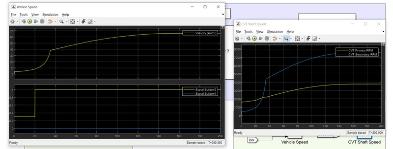
- plots in output are Vehicle speed for break and throttle.
- signal builder is giving as input for brake speed 0 and throttle input from 0.3 to 1.
- IN vehicle speed plot after certain time throttle is increases and velocity increases and reaches to maximum velocity.
- in CVT plot the primary rpm will start at nearly 1700 and ends at 3800.
- secondary rpm will start at nearly 460 and ends at 7600 approximately.now secondary rpm gives higher rpm compared to primary for thr T=200sec.
In this project i took single model and explained because my support engineer told me to explain about any one model.