Project
Objective
1. Study the BAJA ATV model without dashboard
2. Study the BAJA ATV model with dashboard
3. Study the BAJA ATV model using lookup table without dashboard
4. Study the BAJA ATV model using lookup table with dashboard
Study 1
By using simulink model of CVT consists of signal builder,generic engine,motion sensors,vehicle transmission,vehicle body,tyres & solver configuration blocks etc. as shown in figure 1. The CVT subsystem includes transmission block, input and output shaft inertia and motion sensor as shown in figure 2. The vehicle body subsystem includes vehicle body block, double drum brake tyre as shown in figure 3. The initial engine speed is given as 2100 RPM , mechanical rotation for driven pulley and driver pulley as 0.8 & 0.7 respectively.The mass of the vehicle as 250kg and 2 axles which connects four wheels accordingly.
BAJA ATV MODEL
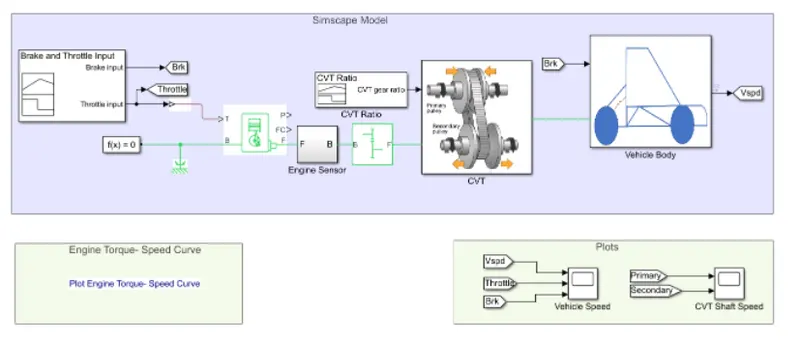
Figure 1
CVT SUBSYSTEM
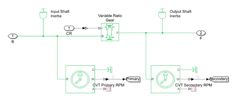
Figure 2
VEHICLE BODY SUBSYSTEM
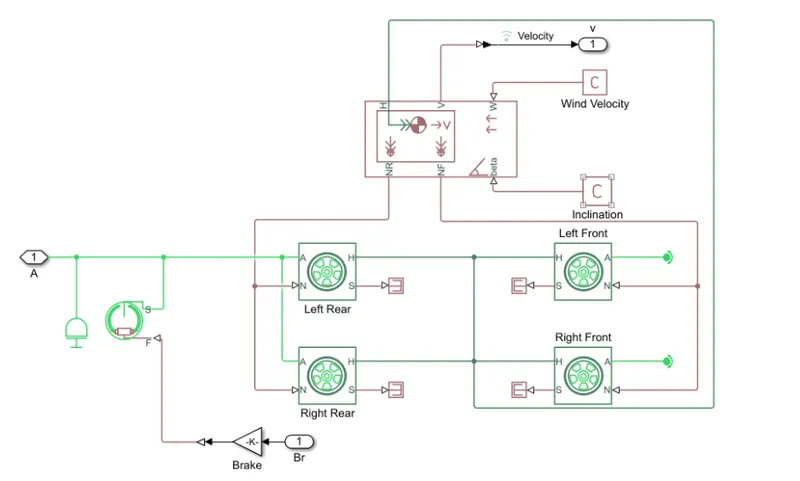
Figure 3
The signal builder is used as input for brake,throttle & gear ratio.Brake input is maintained as 0 for overall simulation. The throttle input is given as 0.3 for 20 secs and increase to 1 for overall simulation. The throttle valve is mainly to control the flow or amount of fuel into the engine. If the throttle value increases the flow of fuel increases to the IC engine which inturn increases the power of the engine.The gear rato is maintained as 2.3 for 5 sec and linearly decraeases to 1.8 and maintained constant for overall simulation as shown in figure.
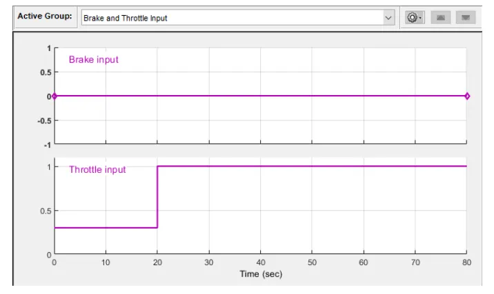
Figure 4
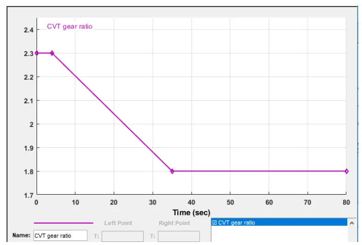
Figure 5
Study 2
BAJA ATV WITH DASHBOARD MODEL
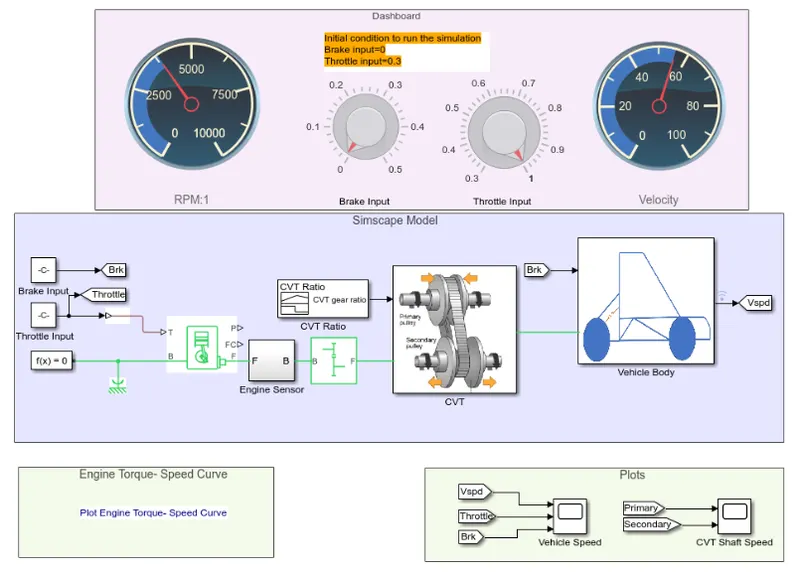
Figure 6
The above figure shows BAJA ATV with dashboard model which consists throttle meter and brake input in the dashboard instead of giving input through signal builder. Rest of the blocks and subsystems are common in the above baja ATV model without dashboard as shown in figure 2 & figure 3. The main concept of using dashboard is study the result by varying the input of brake & throttle , which shows that the velocity & speed of the engine. The gear ratio is maintained as 2.3 for 5 sec and linearly decrease to 1.8 and maintained constatnt for overall simulation as shown in figure 5. As the brake input varies from 0-0.5,the velocity & speed decreases accordingly.By increasing the throttle , the velocity and speed of the engine & shaft increases.
Study 3
By using simulink model of consists of step time, generic engine, motion sensors, vehicle transmission, vehicle body, tyres & solver configuration block as shown in figure 7. The CVT subsystem includes lookup table , transmission block, input & output shaft inertia and motion sensors as shown in figure 8. The vehicle body subsystem includes vehicle body block, double drum brake & tyres as shown in figure 9. The initial engine speed is given as 2100 Rpm, mechanical rotation for driven pulley nad driver pulley is 0.8 & 0.7 respectively. The mass of the vehicle is 250 kg & 2 axles which connects 4 wheels accordingly.
A lookup table is an array of data that maps input values to output values , thereby approximating a mathematical function. Given a set of input values , a lookup operation retrieves the corresponding output values from the table. If the lookup table doesnot explicitly define the input values , simulink can estimate an output value using interpolation, extrapolation or rounding, where
- An interpolation is a process for estimating values that lie between known data points
- An extrapolation is a process for estimating values that lie beyond the range of known data points
- A rounding is a process for approximating a value by altering its digits according to a known rule
BAJA ATV MODEL USING LOOKUP CHART
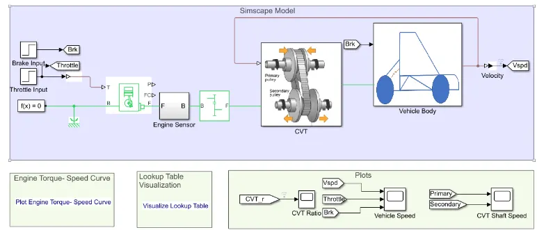
Figure 7
CVT SUBSYSTEM
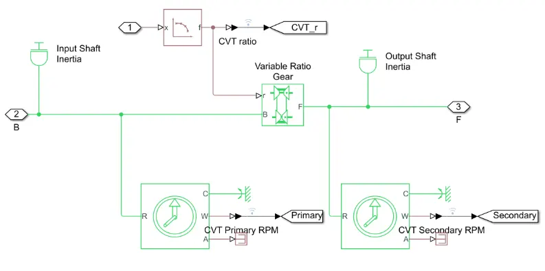
Figure 8
VEHICLE BODY SUBSYSTEM
Figure 9
The brake input and throttle input is given by step time , which depends on the runtime and varries accordingly. By using lookup table for gear ratio which takes as input to the CVT and works according to the input gear ratio and obtained the output. This method is very effective which can avoid the unusal torque at the certain speed and very easy to achieve greater velocity & engine speed. It works as closed loop when the input is given by lookup table.The simulimk get the input value from the lookup table and obtain the result according to the input values of gear ratio. The gear ratio varries from 2.3 to 1.8 as taken as input & output interms of velocity.The maximum velocity reached 57 kmph approximately.
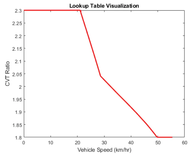
Figure 10
STUDY 4
BAJA ATV MODEL WITH DASHBOARD USING LOOKUP TABLE
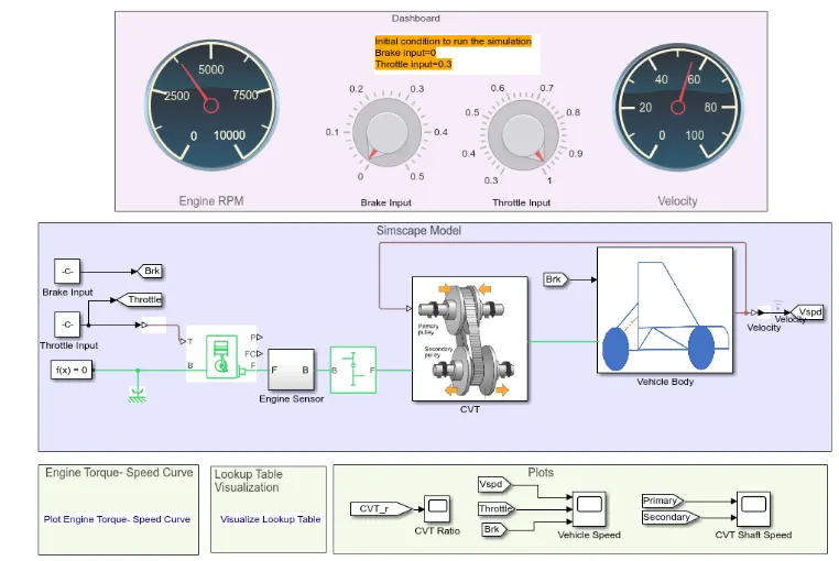
Figure 11
The above figure shows 'Baja ATV with dashboard' model using lookup table which consists throttle meter & brake input in the dashboard & indicated as constant block.Rest of the blocks & subsystem are common in the above baja atv model without dashboard as shown in figure 8 & 9. The main concept of using dashboard is study the result by varying the input of brake & throttle, which shows the variation of velocity & speed of the engine. The gear ratio is given by lookup table. The simulimk get the input value from the lookup table and obtain the result according to the lookup table. As the brake input varies from 0-0.5,the velocity & speed decreases accordingly which inturn the gear ratio also decreasing. By incraesing the throttle the valocity and speed of the engine and shaft increases. The transmission as primary pulley & secondary pulley , in which the radius of the primary pulley increases by compacting and the radius of secondary pulley decreases. As the gear ratio varies , the torque also varies.Gear rato is directly proportional to the torque, which increases by increasing gear ratio. At max torque , the speed & velocity decreases.
OUTPUT
Study 1: Variation of velocity & shaft speed
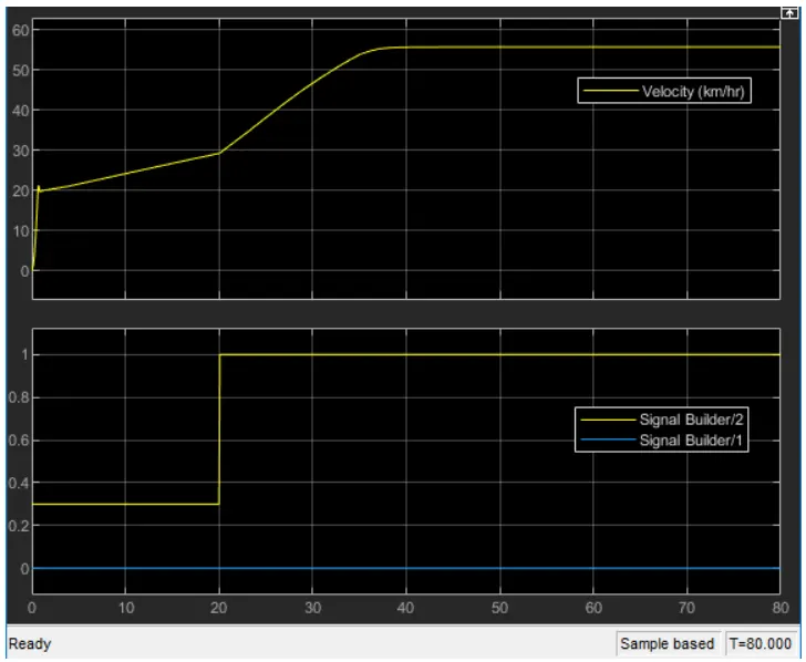
Figure 12
In the above figure, brake is maintained as constant & increase in throttle which shows increase in velocity. The flow of fuel is increasing when the throttle increases from 0.3 to 1, thus the power in the engine increases. The torque reaches approximately 7 Nm at 1.8 gear ratio, which defines that gear ratio is directly propertional to the torque. By this gear ratio , the speed & velocity achieve maximum.
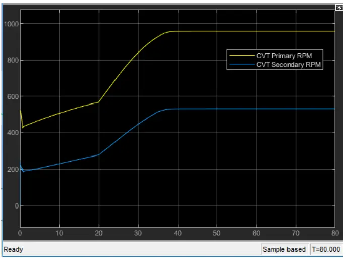
Figure 13
In the above figure , the primary shaft reaches high speed and secondary shaft as low rotational speed because the radius of the primary shaft as more than the secondary shaft, the speed is directly proportional to the radius of the shaft. As the radius increases speed of the shaft also increases.
Study 2: Variation of velocity & shaft speed
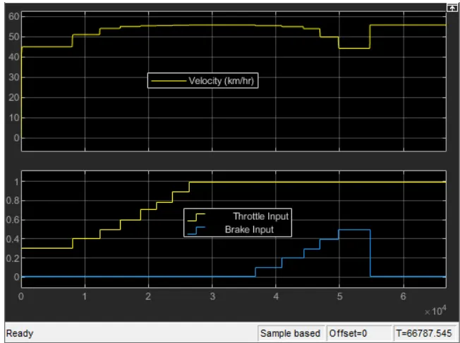
Figure 14
In the above figure ,the velocity of the vehicle is maintained as constant for constant throttle value as 0.3 & varying by increasing the value of throttle which increases the velocity of vehicle. By increasing the brake input, the velocity of the vehicle decreasing accordingly which shown in figure 14.
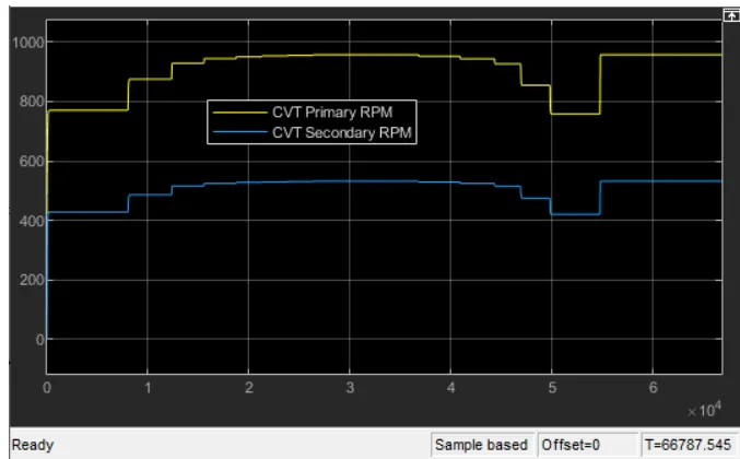
Figure 15
In the above figure, the primary shaft speed increases by increasing throttle and decreasing by increasing brake input value, which defines that throttle can flow more amount fuel which increases the power of the engine and similar to the secondary shaft. The radius of the primary shaft as more tan the secondary shaft , the speed is directly proportional to the radius of the shaft. As the radius increases speed of the shaft also increases.
Study 3: Variation of velocity & shaft speed
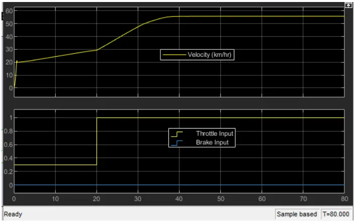
Figure 16
In the above figure the brake is maintained as constant & increase in throttle which increases in velocity. The flow of fuel increases when the throttle increases from 0.3 to 1, thus the power in the engine increases. The torque reaches approximately 7 Nm at 1.8 gear ratio, which defines that gear ratio is directly proportional to the torque. By this gear ratio, speed & velocity can achieve maximum. The gear ratio is assigned in lookup table and given as input to the simulink which reads every input value and obtain the result according to the input.
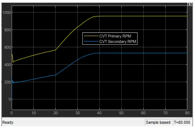
Figure 17
In the above figure primary shaft speed increases by increasing throttle and decreasing by increasing brake input value, which defines that throttle can flow more amount of fuel which increases the power of the engine and similar to the secondary shaft. The radius of the primary shaft as more than secondary shaft , the speed is directly proportional to the radius of the shaft. As the radius increases, the velocity of the shaft also increases.
Study 4: Variation of velocity & shaft speed
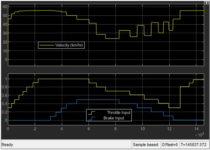
Figure 18
In the above figure, the velocity of the vehicle is maintained as constant for constant throttle value as 0.3 and varying by increasing the value of throttle which increases the velocity of vehicle. By increasing the brake input,the velocity of the vehicle decreasing accordingly which shown in figure 18. By using lookup table, it works as closed loop by recording the velocity value and we can get at any particular value of gear ratio which is beyond the range or any random value within the range by using extrapolation & interpolation by lookup table.
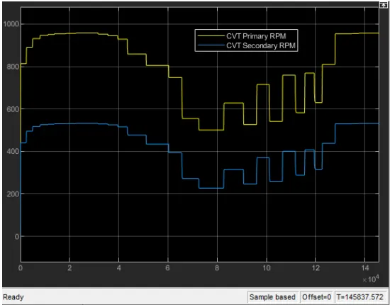
In the above figure, the primary shaft speed increases by increasing throttle and decreasing by increasing brake input value,which defines that throttle can flow more amount of fuel which increases the power of the engine and similar to the secondary shaft.The radius of the primary shaft as more than the secondary shaft, the speed is directly proportioanl to the radius of the shaft. As the radius increases the speed of the shaft also increases. The throttle value and brake input value can be varying in dashboard, so we can get any particular value for input.