Project
Aim: To carry out a system-level simulation of an all-terrain vehicle.
Objective: To prepare a technical report of the model explanation & to analyse the results.
Theory:
All-terrain Vehicle:
- An all-terrain vehicle (ATV), also known as a light utility vehicle (LUV), a quad bike, or simply a quad is a vehicle that travels on low-pressure tires, with a seat that is straddled by the operator, along with handlebars for steering control. It is designed to handle a wider variety of terrain than most other vehicles.
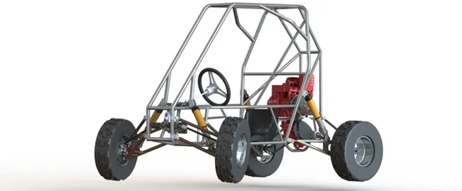
Figure 1
Baja:
- Baja SAE is an Collegiate Design Series competition run by the Society of Automotive Engineers International (SAE International). Teams of students from universities all over the world design and build small off-road cars. The cars all have engines of the same specifications. As of 2018 the engine has been an unmodified Briggs & Stratton Model 19 Vanguard engine single-cylinder with a displacement of 305cc and power output of approximately 10 bhp (7.5 kW).
- The goal in Baja SAE racing is to design, build and race off-road vehicles that can withstand the harshest elements of rough terrain. The vehicles used in Baja SAE racing are often similar in appearance to dune buggies.
CVT:
- A continuously variable transmission (CVT) is an automatic transmission that can change seamlessly through a continuous range of gear ratios. This contrasts with other transmissions that provide a limited number of gear ratios in fixed steps. The flexibility of a CVT with suitable control may allow the engine to operate at a constant RPM while the vehicle moves at varying speeds.
- CVTs are used in automobiles, tractors, motor scooters, snowmobiles, bicycles and earthmoving equipment.
- The most common type of CVT uses two pulleys connected by a belt or chain; however, several other designs have also been used at times.
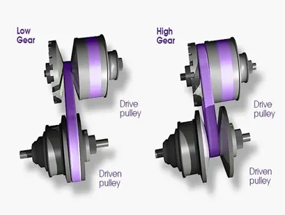
Figure 2
Model-1: BAJA ATV model
- BAJA ATV model using CVT is shown below in Figure 3.
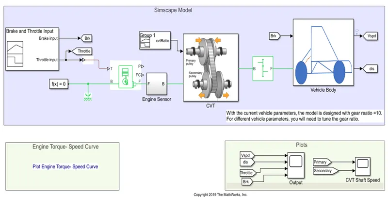
Figure 3
- The signal builder block is used to generate signals for throttle & brake.
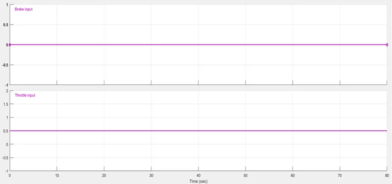
Figure 4
- These signals are given to the inputs of generic engine block. The throttle input signal T lies between zero and one and specifies the torque demanded from the engine as a fraction of the maximum possible torque. Connections F and B are mechanical rotational conserving ports associated with the engine crankshaft and engine block, respectively. Connections P and FC are physical signal output ports through which engine power and fuel consumption rate are reported.
- The torque and speed vectors of generic engine block are inputted from MATLAB workspace.
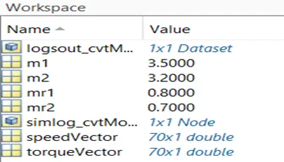
Figure 5
- The engine torque-speed curve is as shown in the below Figure 6.
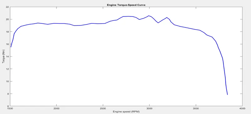
Figure 6
- The F port is connected to an engine sensor which measures the RPM of the engine. The engine sensor subsystem is shown in Figure 7 & the engine RPM is shown in below Figure 8.
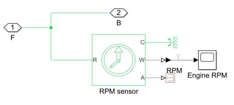
Figure 7
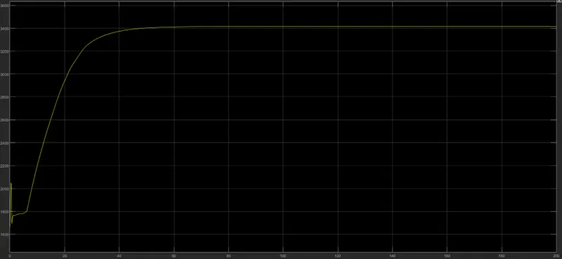
Figure 8
- The CVT block having a subsystem shown in Figure 9 is used to produce variable transmission output.
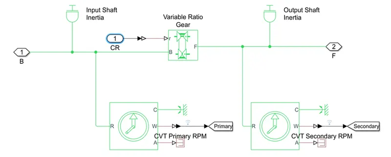
Figure 9
- In variable ratio gear, input shaft is on primary pully and output shaft is on secondary pully. Both shafts are connected to ideal rotational motion sensors to measure their respective angular velocities. The output of these sensors is shown in Figure 10.
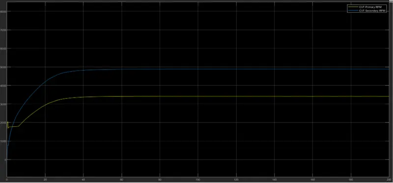
Figure 10
- The r port of variable ratio gear is given a signal from a signal builder block. The given signal provides various gear ratios to the variable ratio gear block.
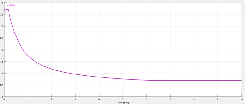
Figure 11
- The output of CVT block is given to a simple gear block with fixed gear ratio of 10.
- The output of simple gear block and the brake signal from signal builder block are given to the input of vehicle body block whose subsystem is shown below in Figure 12.
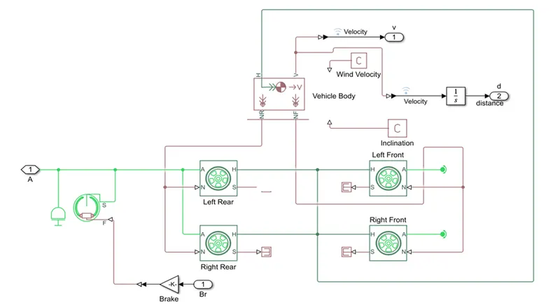
Figure 12
- The vehicle body block represents a two-axle vehicle body in longitudinal motion. The block accounts for body mass, aerodynamic drag, road incline, and weight distribution between axles due to acceleration and road profile.
- Connection H is the mechanical translational conserving port associated with the horizontal motion of the vehicle body. The resulting traction motion developed by tires should be connected to this port. Connections V, NF, and NR are physical signal output ports for vehicle velocity and front and rear normal wheel forces, respectively.
- The double-shoe brake is applied to left and right rear wheels.
- Tire blocks represents the longitudinal behaviour of a highway tire characterized by the tire Magic Formula.
- The parameters of these blocks are shown in below Figures.
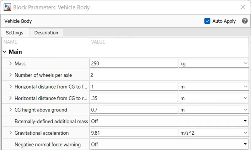
Figure 13: Vehicle body
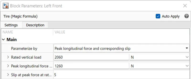
Figure 14: Tire
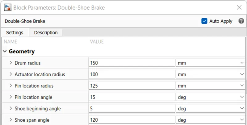
Figure 15: Double-shoe brake
- The outputs of this block are vehicle speed and distance travelled by the vehicle.
- Figure 16 shows different input and output parameters of the model.
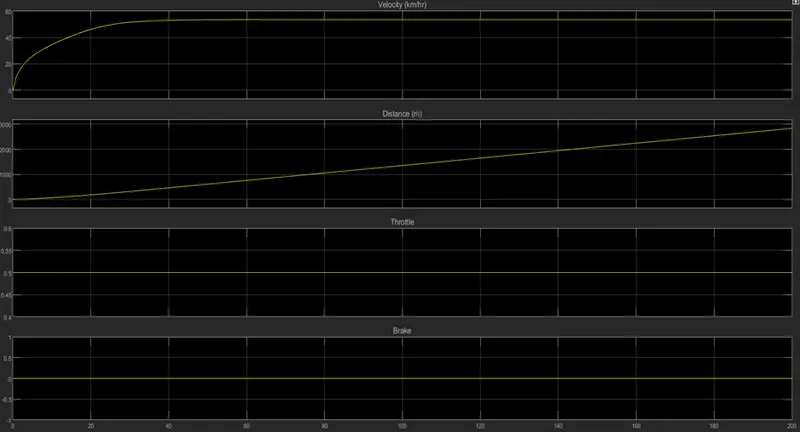
Figure 16
Model-2: BAJA ATV model with dashboard
- Model-1 and model-2 are same with only one difference. In model-1, signal builder block was used to generate throttle and brake inputs but here in model-2, knobs are used to provide such inputs in real time. Circular gauge blocks are also used to display real time velocity and RPM of the vehicle.
- This model is shown below in Figure 17.
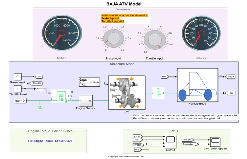
Figure 17
- Figure 18 shows the results of velocity, distance, throttle and brake after the simulation. It can be seen that as throttle input is increased, velocity of the vehicle also increases. Also, when brakes are applied, velocity of the vehicle reduces accordingly.
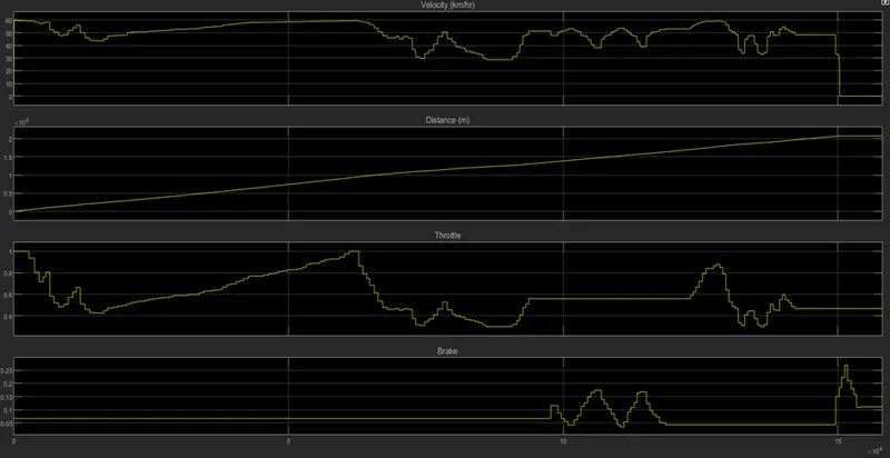
Figure 18
- Figure 19 shows the engine torque-speed curve. It is same as that of in model-1.
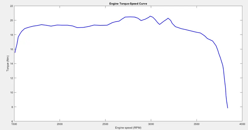
Figure 19
- Figure 20 shows CVT primary & secondary RPM plots. As can be seen, secondary RPM are higher than that of primary. Both curves look identical to each other but just different in magnitude.
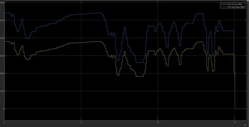
Figure 20
Model-3: BAJA ATV model with lookup table
- Model-1 and model-3 are same with only one difference. The difference being that model-3 uses a lookup table instead of a signal builder block to provide different CVT ratios to the CVT block.
- A lookup table is an array of data that maps input values. This is done so as to approximate a mathematical function. When a set of input values are known, a lookup yields an output value corresponding to each input from a table of values.
- Step inputs are given for throttle and brakes.
- The model-3 is shown in Figure 21 below.
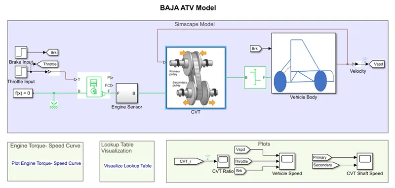
Figure 21
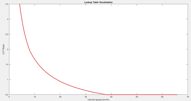
Figure 22
- Figure 22 shows lookup table visualization. It can be seen from the graph that for a particular CVT ratio, vehicle has a speed corresponding to it.
- The CVT primary and secondary RPM are shown in Figure 23.
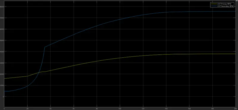
Figure 23
- The vehicle velocity, throttle and brake plots are shown in Figure 24.
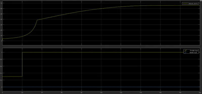
Figure 24
Model-4: BAJA ATV model with lookup table & dashboard
- Model-2 and model-4 are same with only one difference. The difference being that model-4 uses a lookup table instead of a signal builder block to provide different CVT ratios to the CVT block.
- The model-4 is shown in the Figure 25.
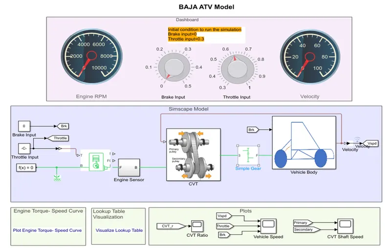
Figure 25
- The CVT primary and secondary RPM plots are shown in Figure 26.
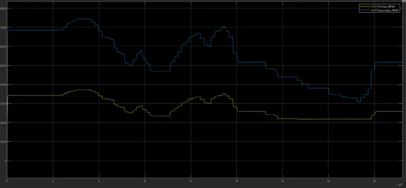
Figure 26
- The output is shown in the below Figure 27.
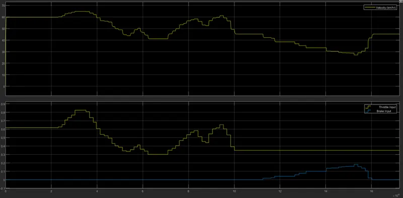
Figure 27
- From Figure 27, it can be seen that as throttle value is increased, the velocity of the vehicle also increases. Also, when brake is applied, the velocity of the vehicle decreases accordingly.
Conclusion:
From the simulation of model-2 and model-4, it can be observed that giving inputs in real time gives output closer to real life scenarios. Understanding of CVT has been improved.