Project
AIM :
To study and investigate the BAJA All-Terrain Vehicle (ATV) utilizing the Simulink model.
OBJECTIVE :
To Prepare a specialized report making sense of the model properties and remarks on the outcomes.
Hypothesis :
Off-road Vehicle
An off-road vehicle (ATV), otherwise called a quad, as characterized by the ANSI is a vehicle that moves on low-pressure tires, with a seat that is ridden by the administrator, alongside handlebars for directing control. As the name suggests, it is intended to deal with a more extensive assortment of landscapes than most other vehicles. Although it is a road lawful vehicle in certain nations, it isn't road legitimate inside most states, regions, and territories of Australia, the United States, or Canada. By the ongoing ANSI definition, ATVs are planned for use by a solitary administrator, albeit a few organizations have created ATVs expected for use by the administrator and one traveler.
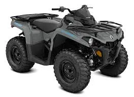
BAJA ATV
Baja SAE is an intercollegiate designing plan rivalry for undergrad and graduate designing understudies. The object of the opposition is to reproduce certifiable design plan projects and their connected difficulties. Each group is contending to have its plan acknowledged for production by an imaginary firm. The understudies should work collectively to configure, assemble, test, advance and contend a vehicle inside the constraints of the standards, likewise to create monetary help for their task and deal with their instructive needs.
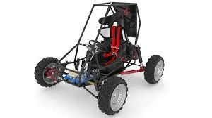
Each group will likely plan and assemble a model of a tough, single-seat, rough terrain sporting vehicle expected available to be purchased to the non-proficient end-of-the-week rough terrain aficionado. The vehicle should be protected, effortlessly shipped, handily kept up with, and amusing to drive. Haggling unpleasant territory without damage ought to be capable. Starting around 2010, the SAE Baja Series comprised of three contests, however, in the past, there have been upwards of seven endorsed occasions. A Baja SAE contest occasion comprises three to four days.
MAJOR COMPONENTS :
Significant COMPONENTS :
Nonexclusive Engine :
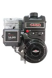
The Generic Engine block addresses an overall inside burning (IC) motor which is a sort of Spark Ignition (SI-Petrol) or Compression Ignition (CI-Diesel). The speed force and speed power boundaries are given.
Ports,
B-Rotational rationing port addressing the Engine Block. level.
F-Rotational rationing port addressing the Engine Crankshaft.
T-Physical sign info port determining the standardized motor choke.
P-Physical sign result port revealing the momentary motor power, in W.
FC-Physical sign result port detailing the fuel utilization rate, in kg/s.
Simple Gear :
The most well-known use is in engine vehicles, where the transmission adjusts the result of the gas-powered motor to the drive wheels. Such motors need to work at a moderately high rotational speed, which is unseemly for beginning, halting, and more slow travel. The transmission decreases the higher motor speed to the more slow wheel speed, expanding force simultaneously. Transmissions are likewise utilized on pedal bikes, fixed machines, and where different rotational velocities and forces are adjusted.
- B- Base Gear, F-Follower Gear.
CVT Transmission :
The importance of the condensing CVT is Continuously Variable Transmission, and it's a sort of single-speed programmed gearbox. The CVT gearbox has been utilized in an assortment of vehicles, yet you'll ordinarily find it fitted to a little vehicle. Its reduced size and effortlessness of development imply it's more financially savvy to use in a little vehicle than an ordinary programmed gearbox. In numerous ways, a CVT gearbox is like a standard auto. First off, there is no grasp pedal in a CVT-prepared vehicle, so you can drive it on a programmed just UK driving permit. You'll likewise view that as assuming a vehicle is presented with a CVT gearbox, it will be more costly than a similar model with a manual gearbox, very much like an ordinary auto. Assuming you contrasted them back with back, the manual model would have better-guaranteed efficiency, as well. In any case, once more, that is equivalent to what you'll find with a normal auto 'box.
- B- Base Pulley
- F- Follower Pulley
- r- Variable Transmission Ratio
Vehicle Body :
A two-pivot vehicle with longitudinal elements and movement and flexible mass, geometry, and drag properties. The vehicle can have something very similar or an alternate number of wheels on every pivot. For instance, two wheels on the front pivot and one wheel on the back hub. The vehicle wheels are expected indistinguishable in size. The vehicle can likewise have a focal point of gravity (CG) that is at or underneath the plane of movement.
NR-Rear pivot ordinary power
NF-Front hub typical power
beta-Road slant point
V-Longitudinal speed
W-Head wind speed
H-Horizontal movement
Double Shoe Brake :
Twofold Shoe Brake :
The Double-Shoe Brake block addresses a frictional brake with two turned unbending shoes that press against a pivoting drum to create a slowing down activity. The unbending shoes sit inside or outside the pivoting drum in an entirely gone against design. A positive activating power makes the unbending shoes press against the pivoting drum. Gooey and contact erosion between the drum and the unbending shoe surfaces cause the turning drum to decelerate.
- S- Rotational conserving port associated with the rotating drum shaft
- F- Physical signal input port associated with the applied actuating force
Tire :
The Vehicle body is connected to 4 tires each per axle to move the vehicle according to the power input to the axle.
- N- Normal force
- S- Tire Slip
- A- Axle
- H- Mechanical translational port
-
Kinds OF MODEL :
BAJA ATV model without Dashboard
BAJA ATV model with Dashboard
BAJA ATV model Lookup table information Extraction
BAJA AV model Mapped Lookup table without Dashboard
BAJA AV model Mapped Lookup table with Dashboard.
#1 BAJA ATV MODEL WITHOUT DASHBOARD
MAIN MODEL :
ENGINE SENSOR :
CVT SYSTEM :
VEHICLE BODY :
FLOW PROCESS :
- The throttle signal is generated by the signal builder block and inputted to the generic engine.
- The torque and speed vector is inputted from the MATLAB workspace.
- The motor will produce the result rpm which can be taken from the driving rod yield. This speed will be given to the Ideal Rotational Motion Sensor to detect the result rpm.
A similar result speed will be given to a straightforward stuff system to lessen the speed where the Gear Ratio is '4'.
Then the resulting speed from the stuff minimizer will be given to the Variable Ratio Transmission block (CVT).
The CVT proportion is given to the Variable Ratio Transmission (CVT) block through Signal Builder.
- The speed is constrained by the variable CVT proportions and the controlled result speed is inputted to the vehicle pivot.
The brake signal is created by the sign manufacturer and inputted to the vehicle body (Double Shoe Brake) for applying the brake to pivot.
- TThe power from the CVT is inputted to the pivot and the vehicle speeds up as per the speed.
Then, at that point, the Velocity is taken as result from the vehicle body for additional examination.
RESULTS :
TORQUE-SPEED PLOT :
The force and speed are inputted from the MATLAB work area window to the conventional motor square to in like manner create the result RPM. This plot is normal for every one of the cases since it's a default contribution to the motor.
ENGINE SPEED PLOT :
Here we can see the motor rpm produced appropriately w.r.t to the choke, speed, and force inputs.
ENGINE SPEED vs GEAR REDUCTION SPEED PLOT :
Here we can see that the motor speed is diminished by the Gear Ratio '4'. For confirmation, I determined the greatest RPM,
Most extreme RPM (Before Reducing) = 3833 rpm
Gear Ratio = 1:4
WKT,
GearRatio=Driven/Driver
1/4=Driven/3833
Driven=3833/4
Driven=958.25RPM
CVT SPEED REDUCTION PLOT
The motor diminished speed is constrained by different CVT Ratios. For confirmation, I had determined the most extreme RPM,
Greatest RPM (Before Reducing) = 958.25 rpm
CVT Ratio = 1:1.8
WKT,
GearRatio=Driven/Driver
1/1.8=Driven/958.25
Driven=958.25/1.8
Driven=532.36RPM
The diminished most extreme rpm is 532.36 rpm which can be confirmed from the plot.
SPEED vs THROTTLE PLOT :
From the diagram, we can gather that the brake isn't applied during the drive cycle and the Throttle is steady (0.3) till 20 sec and is expanded from 0.3 to 1 from 20 sec where it stays consistent all through. With the expansion in choke the vehicle speed likewise increments.
ACCELERATION PLOT :
From the above plot, we can derive that the vehicle is sped up from 0-20 Kmph and afterward continuously increments then it's sped up to 55.74 Kmph where it stays steady all through the cycle.
#2 BAJA ATV MODEL WITH DASHBOARD
MAIN MODEL :
DASHBOARD :
FLOW PROCESS :
The model work process is the same as the course of the 'BAJA ATV model without Dashboard' yet the Throttle and Brake inputs are constrained by the client with the Knob.
RESULTS :
ENGINE SPEED PLOT :
Here the motor speed is created by the data sources like choke, break, force, and speed vectors. The runtime isn't characterized so the Throttle and Break are constrained by the client. The move forward is choked and step down are break inputs.
ENGINE SPEED vs GEAR REDUCTION SPEED PLOT :
Here we can see that the motor speed is diminished by the Gear Ratio '4'. For confirmation, I determined the consistent RPM (42000-50000 sec),
Most extreme RPM (Before Reducing) = 2759.3 rpm
Gear Ratio = 1:4
WKT,
GearRatio=Driven/Driver
1/4=Driven/2759.3
Driven=2759.3/4
Driven=689.825RPM
The decreased consistent rpm is 689.825 rpm which can be checked from the plot.
CVT SPEED REDUCTION PLOT :
The motor decreased speed is constrained by different CVT Ratios. For check, I had determined the steady RPM (42000-50000 sec),
Greatest RPM (Before Reducing) = 689.825 rpm
CVT Ratio = 1:1.8
WKT,
GearRatio=Driven/Driver
1/1.8=Driven/689.825
Driven=689.825/1.8
Driven=383.23RPM
The decreased greatest rpm is 383.23 rpm which can be confirmed from the plot.
SPEED vs THROTTLE PLOT :
From the diagram, we can construe that the vehicle is speeding up while the choke is applied (Step Up) and decelerated while the break is applied (Step Down).
ACCELERATION PLOT :
From the diagram, we can derive that the vehicle is sped up to 46 Kmph at first, and afterward the state changes when the client controls the choke and brake handles. The move forward and venture down are speed increase and deceleration separately. The direct one is the steady speed so no progressions in a choke or slowing down.
#3 BAJA ATV MODEL - LOOKUP TABLE DATA EXTRACTION
SIMULINK MODEL :
FLOW PROCESS :
The model work process is the same as the course of 'BAJA ATV model without Dashboard'. The little expansion is here the CVT Ratio and Vehicle Speed information are separated utilizing the 'To Workspace' block.
RESULTS :
The outcomes are the same as the 'BAJA ATV model without Dashboard' yet an extra result is the CVT Ratio and Vehicle Velocity to the Workspace.
WORKSPACE - BEFORE WORKSPACE-AFTER
They both are exported to the workspace,
The exported data are then considered for further analysis.
#4 BAJA ATV MODEL – MAPPED LOOKUP TABLE WITHOUT DASHBOARD
MAIN MODEL :
CVT SYSTEM :
FLOW PROCESS :
- The model work process is the same as the course of 'BAJA ATV model without Dashboard'.
Rather than Signal Builder Blocks for Brake and Throttle Input the Step blocks are utilized. At 35 sec the brake information will make a stride of significant worth '0' and at 20 sec choke information will increment from 0.3-1 and then, at that point, stays consistent all through.
- And on second thought of Signal Builder Block for CVT Ratio the 2-D Lookup Table is utilized. The additions and extrapolation techniques are set to straight.
- iv. At last the vehicle speed yield is given as criticism to the 2-D Lookup Table so we can confirm that the speed of the vehicle is changing impeccably when the CVT Ratio changes. The vehicle speed is switched over completely to m/s from Kmph.
RESULTS :
CVT RATIO PLOT :
Whenever we analyze the above plot, the proportion changes from 2.3 - to 1.8 inside a stretch of time of 80 sec which is the same as the past BAJA ATV Models. Also, from 32 sec it's a consistent proportion of '1.8'.
CVT RATIO vs VEHICLE VELOCITY :
Here the CVT Ratio changes from 2.3 - 1.8 and the speed esteem likewise changes w.r.t to the CVT Ratio. Subsequently, we can infer that the vehicle speeds up, decelerates, and stays consistent when the CVT Ratio is being shifted. And furthermore, the vehicle accomplishes a steady speed of 55.441m/s.
#5 BAJA ATV MODEL – MAPPED LOOKUP TABLE WITH DASHBOARD
SIMULINK MODEL :
DASHBOARD MODEL (SIMULATION OFF)
DASHBOARD MODEL (SIMULATION ON) :
FLOW PROCESS :
The model work process is the same as the course of 'BAJA ATV model - planned query table without Dashboard' however the Throttle and Brake inputs are constrained by the client with the Knob followed by the vehicle speed is given as criticism to the CVT Ratio query table.
RELATIONSHIP OF CVT RATIO, THROTTLE, AND BRAKE INPUTS :
The relationship with Throttling, Braking, and Change in CVT Ratio respectively is,
In this BAJA ATV Model, the Engine is pre-set to run at 3300 rpm with the choke worth of '0.3'. What's more, the speed at 45 m/s. The CVT ratio for the least and most extreme speed of the motor was re-characterized as 2.3 and 1.8 individually. Whenever the reproduction is begun the underlying choke esteem of 0.3 is accomplished with the goal that the CVT Ratio is close to 1.85. At the point when the choke is being expanded the CVT Ratio move towards 1.8 where the state is the greatest motor speed. At the same time when the choke is diminishing the CVT proportion will move towards 1.85. While the slowing down is applied the CVT Ratio increments so it can accomplish the closest condition of 2.3 (Minimum Engine Speed). While slowing down is decreased the CVT Ratio move towards 1.85 which is the fundamental choke input 0.3 or then again assuming some other choke esteem is applied it would arrive at that CVT Ratio state.
CVT RATIO PLOT :
RESULTS :
ENGINE SPEED PLOT :
From the chart we can gather that the vehicle was first running at least rpm of 3300 rpm and afterward choke is applied (move forward) then slowing down (venture down) then, at that point, the brake is delivered so motor rpm is expanded then slowing down is applied. At last choke and brake are put to a steady of 2900 rpm.
CVT SPEED PLOT :
From the above diagram, we can comprehend that the choke is applied (move forward) and afterward kept steady then slowing down is applied (venture down) then, at that point, the brake is delivered so the motor speed is expanded with expansion in choke input.
INPUT vs VEHICLE SPEED :
From the plot, we can deduce that when the choke is applied the vehicle speed increments, and when the brake is applied vehicle speed diminishes at the same time.