Project
aim:
To prepera a techical report of a system-level simulation of an all-terrain vehicle.
objective:
- analaze the cvt model for given link
- aware of all the block used in model
- test run the model and analyza scope
- provide a proper technical report per the model
system-level simulation of an all-terrain vehicle
1.ALL TERRAIN VEHICLES:
- an all terrain vechicle ATV, also known as a light utility vechicle LUV a quad bike , or simply a quad. is a vechicle that travels on low-pressure tires,with a seat that is staddled by the operator, along with handlebars for steering control. as the name implies, it is designed to handel a wider variety of terrain than most other vechicles. although its a street legal vehicle in some countries, its a street legal vechicle in some countries its not street legal within most states , territories and provinces of australia, the united states or canada.
- by the current ANSI definition ATVs are intended for use by a single operator although some companies have developed ATVs intended for use by operator and one passenger . ATVs are reffered to as tandem ATVS.
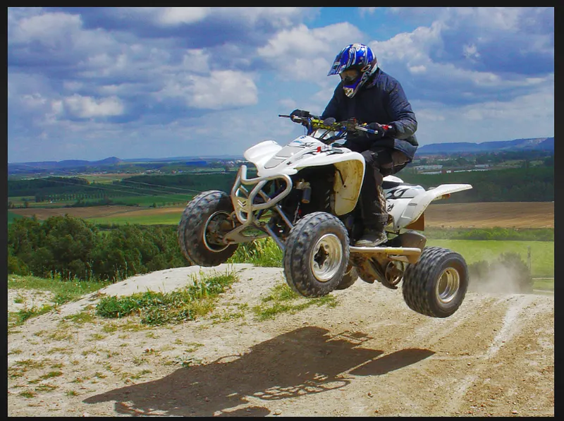
- Royal enfield buit and sold the first poweed quadracycle in 1893. it had many bicycle components, including handle bars. royal enfield resembles a modern ATV-style quad bike but was designed as a from of horseless carriage foe road use.
2.CONTINUOUSLY VARIABLE TRANSMISSION(CVT)
- a continuously variable transmission is an automatic transmission that can change seamlessly though a continuous range of gear ratios. this contrasts with other transmissions that provide a limited number of gear ratio in fixed steps.flexibility of a CVT with suitable controll may allow the engine to operator at constant rpm while the vechile moves at varying speed.
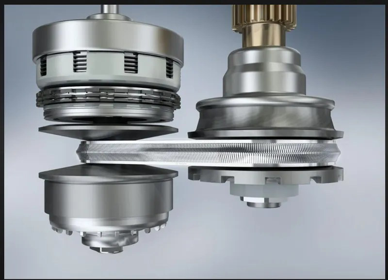
- CCTs are used in automobiles, tractors,motor scooter,snowmobile and earthmoving equipemt. the most common type of CVT uses two pulleys connected by a belt or chain , however, several other design have also been used at tiime.
MODEL:
CVT of terrain vehicle:
EXPLANATION:
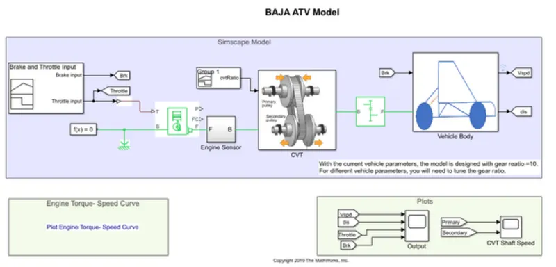
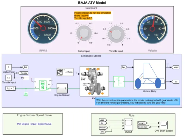
- in this baja ATV model, essentially both of simulink and simscape blocks has used in it. these blocks came up with the rrefernece calculation of previous models in baja ATV.
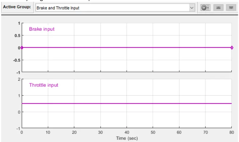
- here we going analyze these technical block which are used to design this continuously variable transmission CVT. from beginning the siganl builder block has used to send the inputs of 'brake' and 'throttle' aare 0 and 0.5 by the time of 80sec.
- simple concept is we going analyze the amount of output (rpm) by giving the amount of input( throttle), that why we gives the brake inputs as 0.
- now the throttle inputn of simulink signal has have to convwert into physical signal, we going to connent the simulink -ps converytor with the output of signal builder .
- it sends to generic engine block as input , this block has represents a system level model of spark-ignition and diesel engines suitable for use at initial stage of modeling when only the basic parameters are available. idle speed and red line controllers are included.
- here T is the input,B is connected with mechanical rotational referenrcre block to connent the mechanical rotational ports that are rigidly affixed to the frame (ground), F is the output of the engine and remaninig are the free ends. slover configuration block has connected with that.
- the output of F is connected with the sub-system which is an engine sensor for monitoring the engine speed . RPM sensor block has used in it.
-
- Here,R is the input of this sensor, C is the free end, A is the PS terminator block to terminate physical signal output and W is the output of the sensor, its converts from physical to simulink signal by PS-simulink convertor then its connect with Scope block .
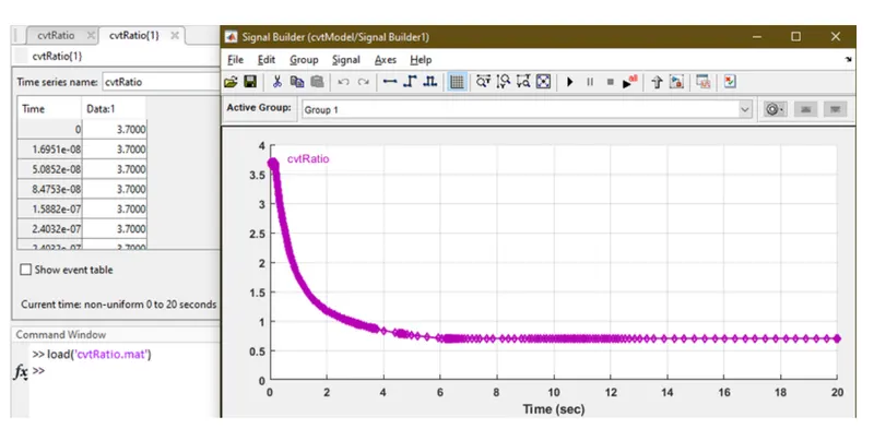
- the output of the sub-system B has passed to the another sub-system of CVT block as respectively . CVT block the input has passed to the signal builder by the reference date file of CVT ratio has given which is loaded by the matlab code.
- the CVT sub-system the variable ratio transmission block has receive input. it has repersent a variable ratio gearbox such as implemented by mechanical bbelt CVT. physical signal input r defines the ratio of input to output angular shaft velocities.
- connection B(base),F(folloer) are mechanical rotational conserving ports. on both sides of rotational conversing parts are connected with the inertia shaft as respectively.
- input and output of inertia has given it repersent an ideal mechanical rotational intertia. commonly in newton law, an object has applied by the external force to change its state , if it doesn't change its state then its known as intertia. so that inertia is basically came up with the mass and dimension of the object.
- for that the inertia block has one or two mechanical rotational conserving ports. the difference is purly graphical as the ports are rigidly linked. block positive direction is from port to the reference point. its mean that the inertia torque is postive if inertia accelerated in the positive direction.
- RPM sensor has connected on the both side (B&F) in the variable ratio gear, were B side is primary RPM and F side is secondary RPM. output of both sensor has take out by the goto block , it send signals to from block that have the specified tag.
- tag visibility is scoped then a goto tah visibility block must be used to define the visibility of the tag. tthat block icon display the selected tag name.
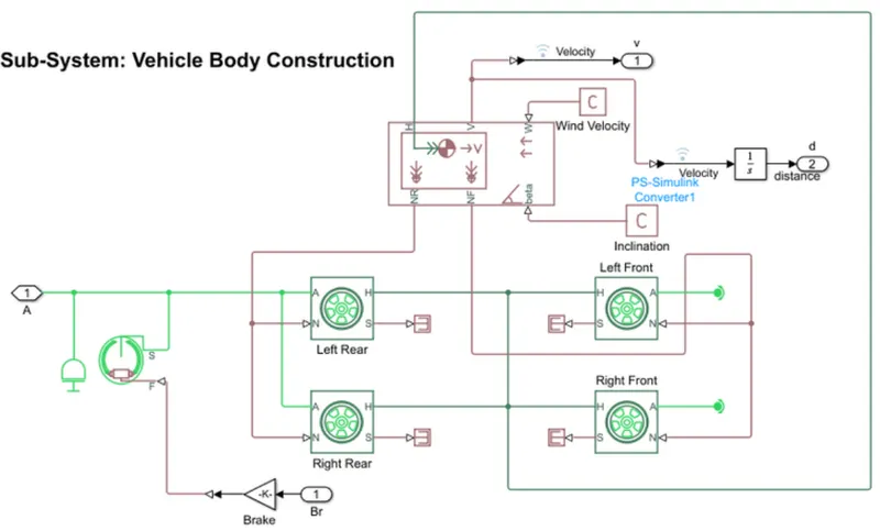
- on above picture, output(F) of CVT has connected with the simple gear block which has represents a fixed ratio gear or gear box.output(F) this block has connected to the sub-system block vehicle body construction.
- in this sub system has vehicle body lock repersents a two -axle vehicle body in longitudinal motion. block accounts for body mass, aerodynamic drag,road incline and weight distribution between axles due to acceleration and road profile.
- now tire block hasgoing to link with the vehicle body block which represent the longitudinal behavior of a highway tire characterized by trhe tire magic formula.
- in vehicle body block, connection W and beta has connected with PS constant block which has creat a physical signal constant, y=constant. the block output is a physical signal port.connection NF and NR are physical signal output ports for vehicle fornt and rear normal wheel force, all are connected with tire block connecction N is physical signal input port .
- tire block ,connection H is the mechanical translational conserving port associated with the horizontal motion of the vehicle body. its conneccted by 4 tire block which repersents the longitudinal behavior of a highway tire charaterized byt magic formula.
- in vehicle body block connection V is physical signal output ports for vehicle velocity forces which has converted into simulink signal by using PS-simulink convertor as respectively. and one more connection from V has again converted into simulink signal by PS-simulink convertor . has passed through integrator block which represent continuous time intergersation of the input signal with initial condition 0.
- now from the tire connection A is mechanical rotational conserving port for wheel axle. its going to be connected with the mechanical rotational free end used it to allow a node to rotate freely without torque.
- rear tires both going to conect with interia and double shoe brake block. double shoe brake block has represent abrake aranged two pivoted rigid shoes symmetrically installed inside or outside a drum and operated by one actuator.
- all connection S-physical signal output port that report that trie slip. tire block has connected with PS terminater block its uses this block to terminate physical signal output.
- from this block connection S is a conserving rotational terminal associated with drum shaft which is from the rear wheel and connection F is physical signal port representing the force input to actuator.
- input has got by brake input with gain block of value 1000.postive force creater friction torque that resists shaft rotation.optionally include thermal effects and expose thermal conserving port H by setting thermal port to model.
- from all technical block the outputs of vehical speed, distance,throttle,brake has conected in a scope and primary secondary output from the CVT sub-system block has connected with another scope as seperately.reference plot output has added in this model which engine torque speed curve.
DASHBOARD OF CVT:
Explanation:
- above CVT dashboard formation has from the previous kind of model . has updated with the additional setup inclued by circular gauges ,knobs. its used to control the input and control the input and has to monitor sensor as respectively.
- here the input of brake and throttle has previously handled by signal builder .now its has replaced with the two constant block which is handled by the knob blocks has placed in the dashboard.
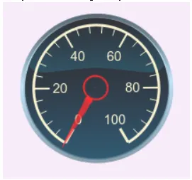
- engine sensor and vechicle body sub-system has monitord by the two circular gauge block of RPM gauge and velocity gauge from the dashboard.block have set with certain amount of limits as per the engine performance.
- there has an initial condition has given to the vechicle input , which is 0 for the brake and 1 for the throttle. so as per the given condition of the input the knobs has to be adjust as manually before the program gets run.
- finally the above all explanation are detailed about the BAJA CTV models working funtion with simulink blocks usage..
GRAPH:
a. engine torque speed curve (plotted with the baja ctv real time output data.
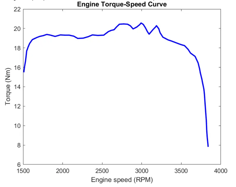
based in real time overall engine performance of baja ctv
b.vehicle speed by distance as per the input,
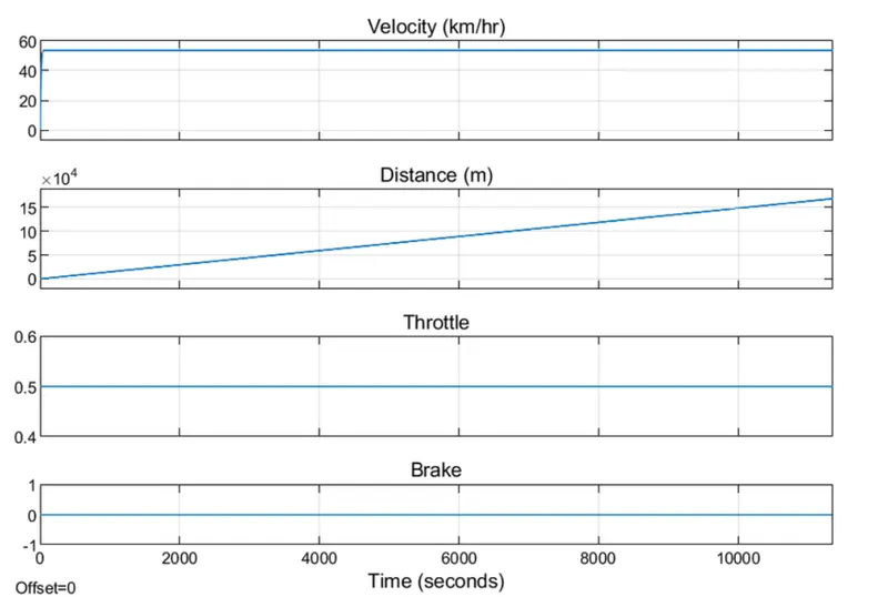
the model designer has not provided the stop time limit and the inputs are also constant. i have took over the output through the maximum change in the circular gauge, velocity and cvt designed with gear ratio as 10
c. cvt shaft speed
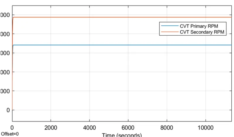
the output has got from cvt sub-system block which shows the constant RPM level both primary and secondary sensor as per the value levels.
conclusion:
- cvt based terrain vechicles working funtion learned as well.
- complete cvt simulation achived through the simiulink.
- overall blocks and sub system used have understood.