Project
AIM:
To study and analyze the BAJA all Terrain Vehicle model using simulink.
OBJECTIVES:
To prepare a technical report of BAJA ATV model with and without lookup table.
ALL TERRAIN VEHICLE(ATV):
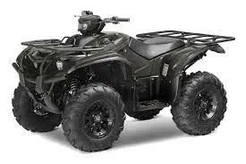
An all-terrain vehicle (ATV), also known as a light utility vehicle (LUV),[1] a quad bike, or simply a quad, as defined by the American National Standards Institute (ANSI); is a vehicle that travels on low-pressure tires, with a seat that is straddled by the operator, along with handlebars for steering control. As the name implies, it is designed to handle a wider variety of terrain than most other vehicles. Although it is a street-legal vehicle in some countries, it is not street-legal within most states, territories and provinces of Australia, the United States or Canada.
By the current ANSI definition, ATVs are intended for use by a single operator, although some companies have developed ATVs intended for use by the operator and one passenger. These ATVs are referred to as tandem ATVs.[2]
The rider sits on and operates these vehicles like a motorcycle, but the extra wheels give more stability at slower speeds. Although most are equipped with three or four wheels, six-wheel models exists and existed historically[3] for specialized applications. Multiple-user analogues with side-by-side seating are called utility terrain vehicles (UTVs) or side-by-sides to distinguish the classes of vehicle. Both classes tend to have similar powertrain parts. Engine sizes of ATVs currently for sale in the United States (as of 2008 products) range from 49 to 1,000 cc (3.0 to 61 cu in).
The Generic Engine block represents a general internal combustion engine. This block is a suitable generic engine for spark-ignition and diesel. Speed-power and speed-torque parameterizations are provided. A throttle physical signal input specifies the normalized engine torque. Optional dynamic parameters include crankshaft inertia and response time lag. A physical signal port outputs the engine fuel consumption rate based on the fuel consumption model that you choose. Optional speed and redline controllers prevent engine stall and enable cruise control.
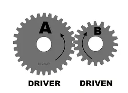
Simple Gear
This example shows a simple gear coupling two inertias (shafts). The gear ratio between the follower (F) and base (B) is 2:1. Thus the angular velocity of the follower shaft is half the angular velocity of the base shaft. The follower shaft torque is twice the base shaft torque.
An alternative to adding sensors to your model is to use Simscape™ data logging. This example has data logging enabled, passing results to the workspace variable 'simlog_sdl_gear'. For example, entering 'plot(simlog_sdl_gear.Gear.B.w)' at the command line plots the angular velocity at port B of the Gear block. See the Data Logging Example in the Simscape User Guide for further details
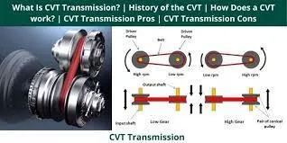
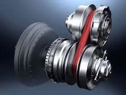
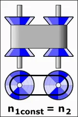
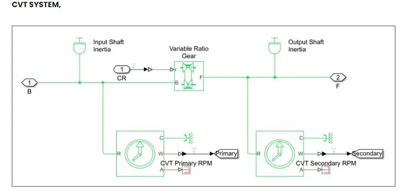
A continuously variable transmission (CVT) is an automatic transmission that can change seamlessly through a continuous range of gear ratios. This contrasts with other transmissions that provide a limited number of gear ratios in fixed steps. The flexibility of a CVT with suitable control may allow the engine to operate at a constant RPM while the vehicle moves at varying speeds.
CVTs are used in automobiles, tractors, motor scooters, snowmobiles, bicycles and earthmoving equipment.
DOUBLE SHOE BRAKE
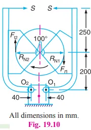
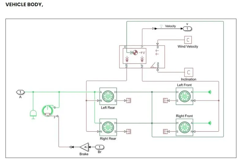
The Double-Shoe Brake block represents a frictional brake with two pivoted rigid shoes that press against a rotating drum to produce a braking action. The rigid shoes sit inside or outside the rotating drum in a diametrically opposed configuration. A positive actuating force causes the rigid shoes to press against the rotating drum. Viscous and contact friction between the drum and the rigid shoe surfaces cause the rotating drum to decelerate.
Double-shoe brakes provide high braking torque with small actuator deflections in applications that include motor vehicles and some heavy machinery. The model employs a simple parameterization with readily accessible brake geometry and friction parameters.
You can also enable faulting. When faulting occurs, the belt will exert a user-specified force. Faults can occur at a specified time or due to an external trigger at port T.
FLOW PROCESS:

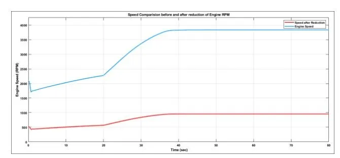
ENGINE SPEED VS GEAR REDUCTION SPEED PLOT
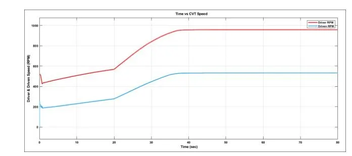
CVT SPEED REDUCTION PLOT
ENGINE SPEED PLOT
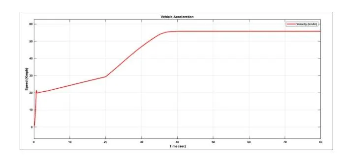
ENGINE SPEED PLOT
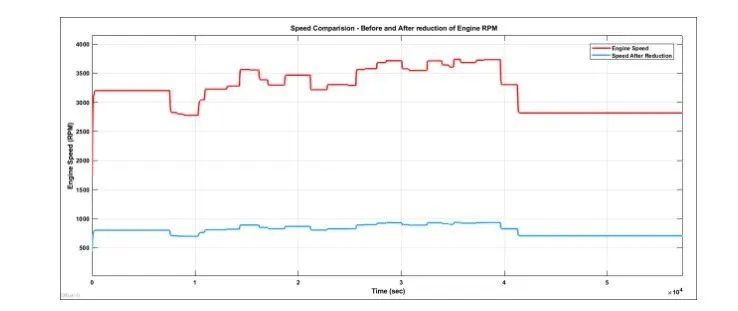
ACCELERATION PLOT
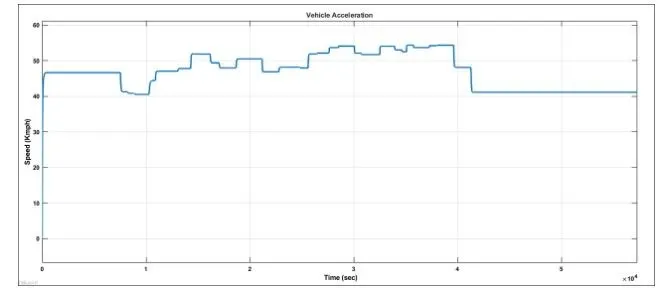
CVT RATIO PLOT
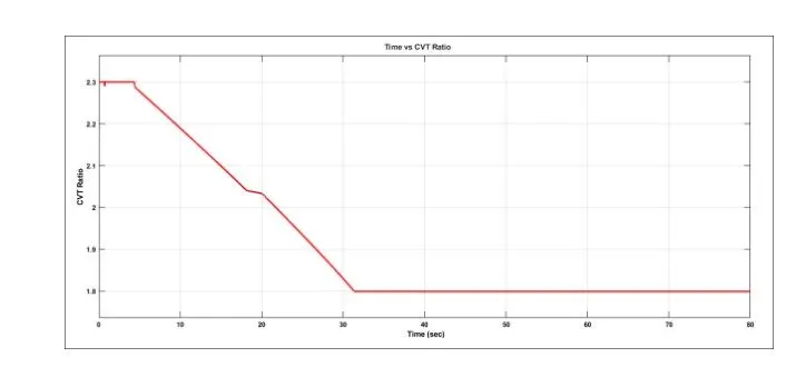
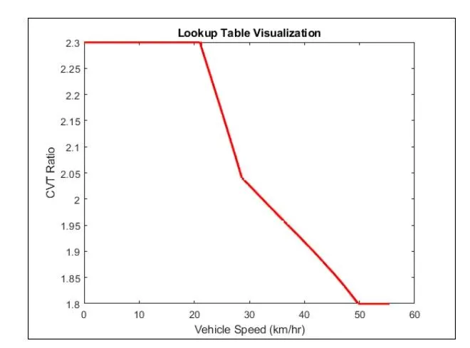
CVT RATIO VS VEHICLE VELOCITY
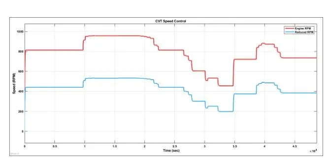
CVT SPEED PLOT
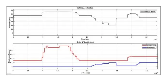
INPUT VS VEHICLE SPEED
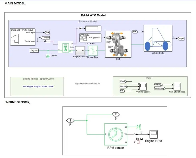
1. The throttle signal is generated by signal builder block and input to ganaric engine.
2. The torque and the speed vector are inputed from matlab work space.
3. The engine will generate the output rpm which can be taken from the crankshaft output.This speeed will be given to the ideal rotational motion sensor to sense the output rpm.
4.The same output speed will be given to simpler gear mechanism to reduce the speed where the gear ratio is 4
5. Then the output speed from the gear reducer will be given to the variable ratio transmission block.
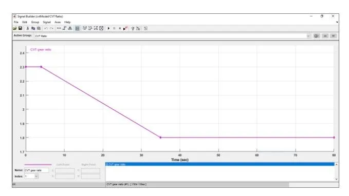
6.The CVT ratio is provided to the variable ratio transmission block througjh signal builder.
7. The speed is controlled by variable cvt ratios and the controlled putput speed is inputted to the vehicle axle.
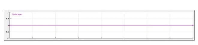
8. The brake signal is generated by the signalbuilder and inputtred to vehicle body for applying brake to axle.
9.The power from the cvt is inputted to the axle and vehicle accelerates according to the speed.
10.Then the velocity is taken as output from the vehicle body for further analysis.
RESULTS
TORQUE AND SPEED PLOT:
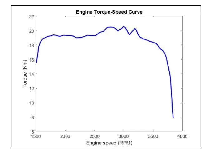
The torque and speed are input from matlab workspace window to generic engine block to generate the output RPM accordingly. This plot is common for all cases because it is a default input to the engine.
Rpm generated wrt the throttle speed and torque inputs.the engine reduced speed is contrilled by various cvt ratios . The brake is not applied during the drive cycle and throttle is constant and being increased with increse in throttle speed also increased.
The vehicle is accelerated and then increases after while it remains constant through the cycle.The engine speed is generated according to the inputs like throttle , brek, torque and speed vectors.There is changes in acceleration but no changes in throttle or braking.
The results are same as baja atv model without dashboard but an additional output is the cvt ratio and vehicle velocity to the workspace.
LEAVE A COMMENT
Theanks for choosing to leave a comment . Please keep in mind that all comments are moderated according to our comment policy and your email address will not be published . Lets have a personal and meaningful conversation.