Project
Objective: To study and explain 'Baja all terrain vehicle' model.
Theory:
Mathsworks brings us the Baja all terrian vehicle model, to study the various components and parameters of vahicle for the students. The model contains relealistic input parameters which has been taken from a Baja team. There are two types of models open loop model and closed loop model. In open loop system output parameters are not synchronised with the input parameters, whereas in closed loop system output parameters are synchronised with input parameters to get maximum efficiency. There are six types of models, which are as follows.
1.CVT model
2.CVT model with dashboard
3.CVT model CVT ratio_rpm
4.CVT model with dashboard mapped
5.CVT model data
6.CVT model mapped
The vehicle consist of following main components.
1.CVT:
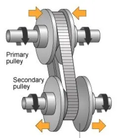
It is contionuously variable transmission. It consist of primary pully, variator, belt,secondary pully. Variator which is connected to primary pully goes outward when variator of secondary pully comes inward such that radius of secondary pully more than the radius of primary pully so that lead to speed reduction. On other hand when variator of primary pully move inward then variator of secondary pully move outward and it will lead to over drive.
2.Engine:
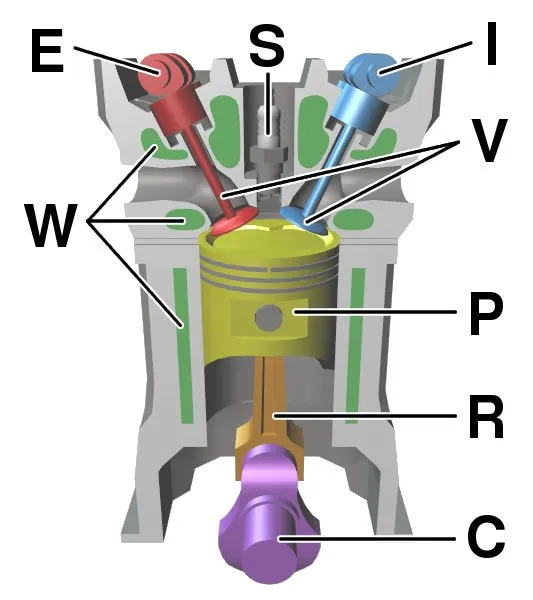
An engine or motor is a machine designed to convert one or more forms of energy into mechanical energy.Available energy sources include potential energy (e.g. energy of the Earth's gravitational field as exploited in hydroelectric power generation), heat energy (e.g. geothermal), chemical energy, electric potential and nuclear energy (from nuclear fission or nuclear fusion). Many of these processes generate heat as an intermediate energy form, so heat engines have special importance. Some natural processes, such as atmospheric convection cells convert environmental heat into motion (e.g. in the form of rising air currents). Mechanical energy is of particular importance in transportation, but also plays a role in many industrial processes such as cutting, grinding, crushing, and mixing.
3.Vehicle body:
Vehicle Body means any moving or non-moving metal components of the vehicle including parts replaced.
4.Suspension:
Suspension is the system of tires, tire air, springs, shock absorbers and linkages that connects a vehicle to its wheels and allows relative motion between the two. Suspension systems must support both road holding/handling and ride quality, which are at odds with each other.
5.Tyre:
A tire (American English) or tyre (British English) is a ring-shaped component that surrounds a wheel's rim to transfer a vehicle's load from the axle through the wheel to the ground and to provide traction on the surface over which the wheel travels.
Following are the models explained in breifly.
1.CVT model:
Block diagram:
Blocks used:
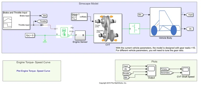
- Signal builder:To input the brake,throttle and CVT ratio.
- Simulink to ps converter:to convert simulink signal to simscape.
- solver configuration:To specify solver parameters before stating simulation.
- Mechanical refrence:To make sure all copmonenets are clamped to ground.
- Generic engine:To give input speed and torque.
- scope:to view the graphs
- Display:To view the results
- Rotational motion sensor:To sense the rpm
- Variable gear ratio:to vary the speed according to gear ratio
- tyres:For transportation of vehicle.
- step:To increase or decrease input value
- Simple gear:To reduce the speed
- Lookup table:To insert CVT values from workspace
- Knob:To increase or decrease the throttle and bkrake input
- Double shoe brakes:To resuce speed
- Rotational free end:For mechanical component
In above model brake input and throttle input is given to the system with help of signal builder. And this signal is further transmitted to the engine.Then the engine connected to the CVT which is connected to vehicle body with help of gear. A CVT ratio is attached to CVT with the hepl of signal builder which is shown as below.
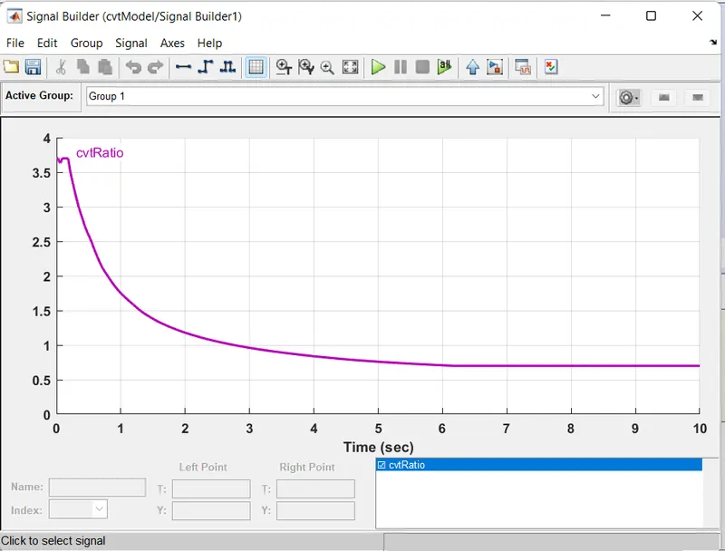
In above fig. we can see that initially there more torque available at shaft but as momumtum increases torque is also decreses.
Throttle and brake input:
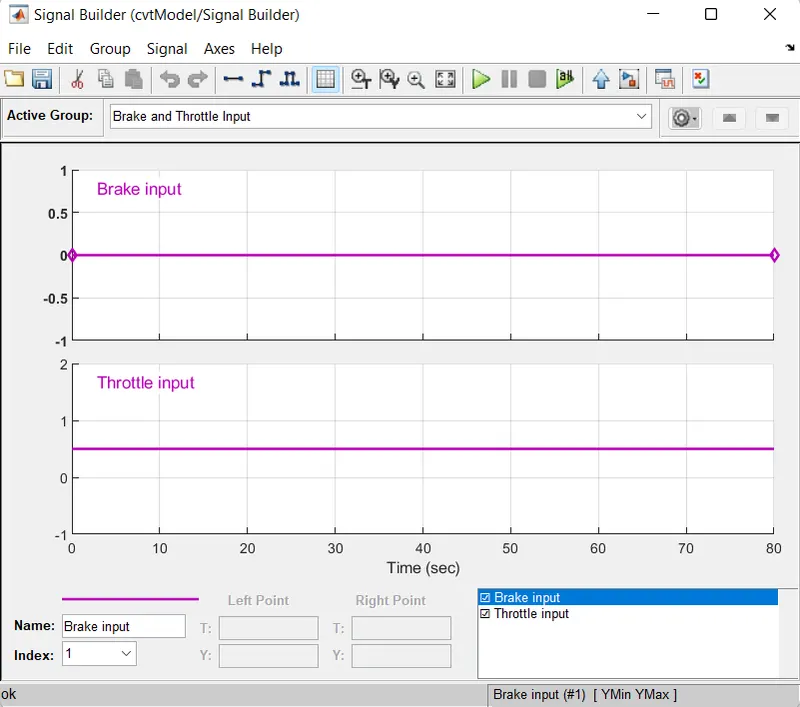
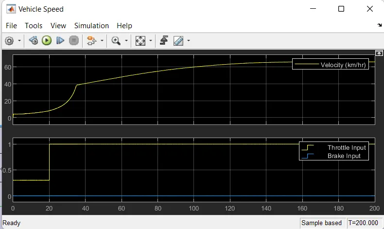
In above fig we can see that brake input is kept at zero and throttle input is kept constant.
Output:
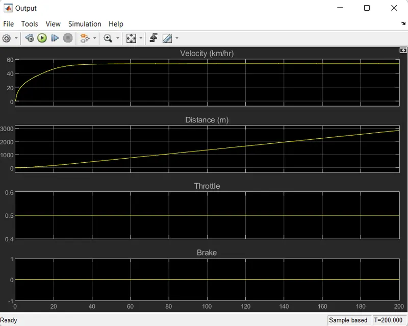
As there is no brakes applied and throttle is constant the velocity is gradually incraesing and when the maximum velocity reached then it moves with constant speed.
2.CVT model with dashboard:
Block diagram:
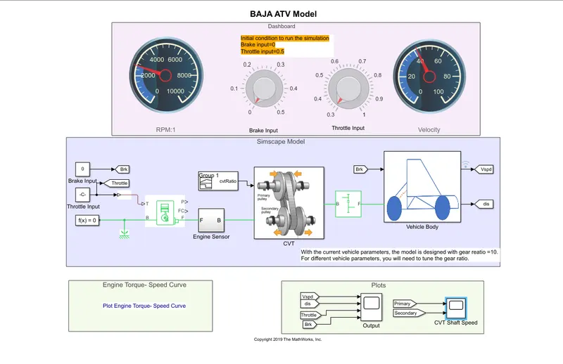
In above block diagram the brake input and throttle input is given manually with the help of two circular knobs. Initially brake input is kept at zero and throttle knob is kept at 0.5. With this conditions simulation is run. During the simulation throttle input is varried so as to check the output.
Output:
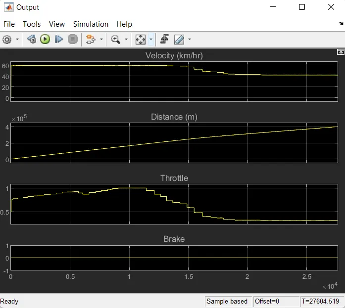
From above results we observe that as throttle input is reduced or increased velocity is also varies.
Closed loop model:
3.CVT model CVT ratio:
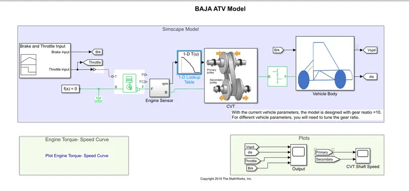
In open loop model we are giving any random data to the system and observing the data but in closed loop system we are connecting the velocity to the CVT block to get more practicle results.
In above block we have used lookuptable and logged it to CVT block and run the model.
Lookup table visualisation:
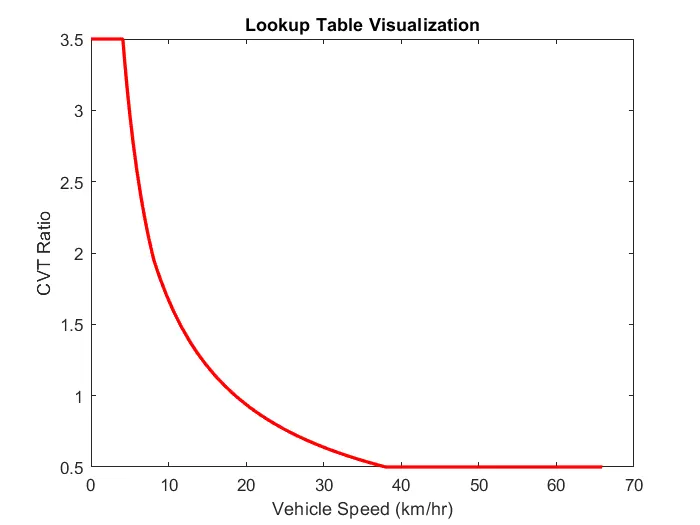
Above fig shows the realistic data for CVT ratio and vehivle speed this data is logged to CVT block.
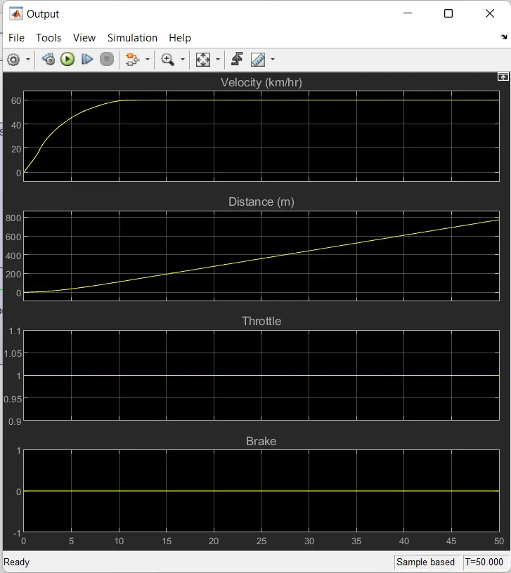
Output:
4.CVT dashboard mapped:
Block diagram:
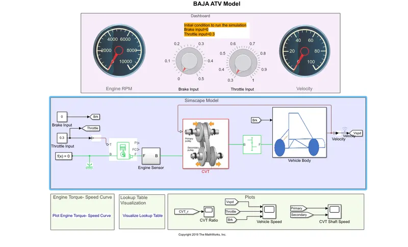
In this model output is mapped with CVT block
Output:
Conclusion:
Above models are very useful to student who are working on Baja project to build their vehicle.