Simulink model of doorbell using solenoid and simulink model of temperature sensor using thermister
Objective: 1)To make a simulink model of door bell using 'solenoid block' qnd observe physical movement of plunger.
2)To sense the temperature of and turn ON ar OFF as per below conditions using Thermister block.
Temperature source: 20 °C from 0 to 10 seconds, 27 °C from 10 to 30 seconds, 23 °C from 30 to 50 seconds
Fan conditions: ON if the temperature above 25 °C, OFF otherwise.
Theory:
Solenoid:
A solenoid is a device comprised of a coil of wire, the housing and a moveable plunger (armature). When an electrical current is introduced, a magnetic field forms around the coil which draws the plunger in. More simply, a solenoid converts electrical energy into mechanical work.
The term solenoid was coined in 1823 by André-Marie Ampère to designate a helical coil.
The helical coil of a solenoid does not necessarily need to revolve around a straight-line axis; for example, William Sturgeon's electromagnet of 1824 consisted of a solenoid bent into a horseshoe shape.
Solenoids provide magnetic focusing of electrons in vacuums, notably in television camera tubes such as vidicons and image orthicons. Electrons take helical paths within the magnetic field. These solenoids, focus coils, surround nearly the whole length of the tube.
In engineering, the term "solenoid" refers not only to the electromagnet but to a complete apparatus providing an actuator that converts electrical energy to mechanical energy.
Thermistor:
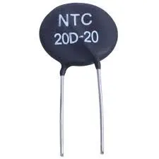
A thermistor is a type of resistor whose resistance is strongly dependent on temperature, more so than in standard resistors. The word is a combination of thermal and resistor. Thermistors are widely used as inrush current limiters, temperature sensors (negative temperature coefficient or NTC type typically), self-resetting overcurrent protectors, and self-regulating heating elements (positive temperature coefficient or PTC type typically). An operational temperature range of a thermistor is dependent on the probe type and is typically between −100 ⁰C and 300 ⁰C (−148 °F and 572 °F).
Block diagram of door bell:-
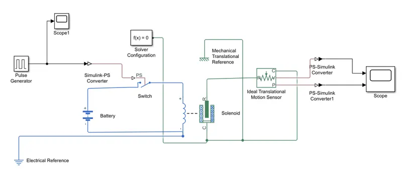
In above block diagram we have used following blocks.
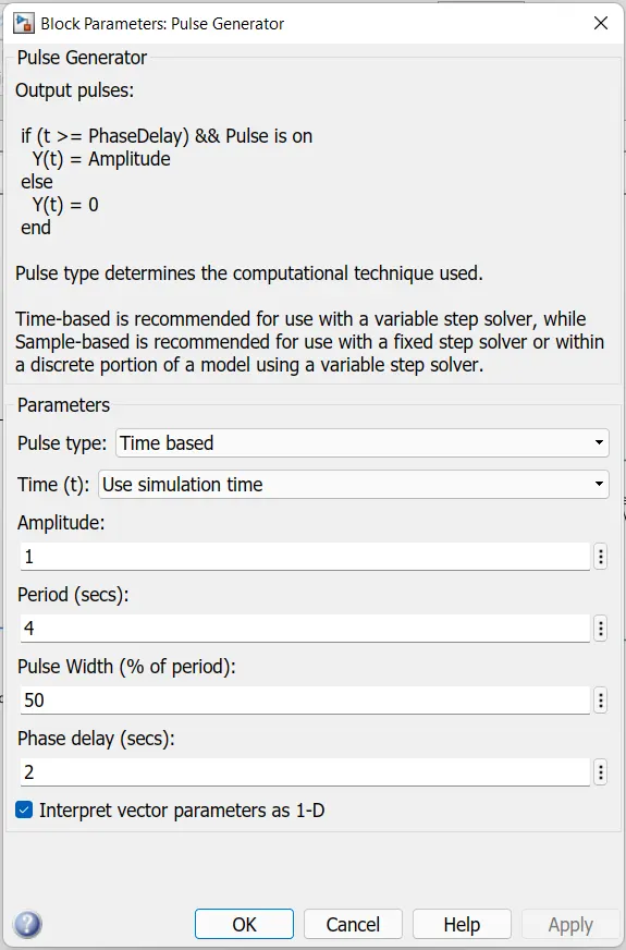
1.Pulse generator:-It is used to generate required input signal. As per requirement we need to on bell for two seconds so to get this situation we have used pulse generator.
2.Battery:-Source of current required to operate circuit.
3.Switch:-For control of ON or OFF condition of current.
4.Solenoid:-It is used to generate mechanical translation movement of plunger.
5.Ideal translation motion sensor:-It is used to sense motion of plunger.
6.Scope:-It is used to view the results or plots.
7.Simulink to ps converter:-Convert Simulink input signal into physical signal.
8.Ps to simulink converter:-Convert physical signal into Simulink output signal.
9.Electrical refrence:-Connection to electrical ground
10.Mechanical translation refrence:-Reference connection for mechanical translational ports
11.Solver configuration:-The Solver Configuration block specifies the solver parameters that your model needs before you can begin simulation
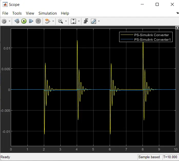
Output:
Conclusion:
From above fig. we can clearly see that the signals generated are after 2sec. And there is movement of plunger.
Block diagram for Thermister challenge:
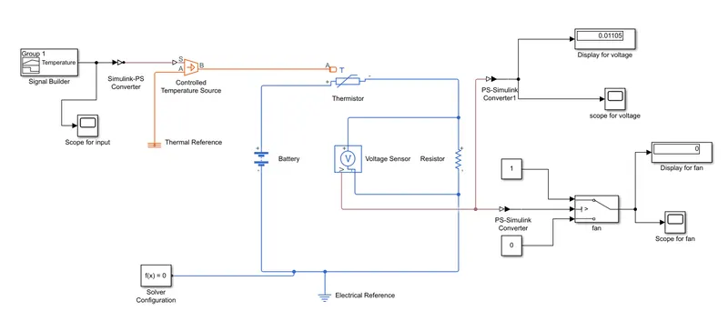
In above fig we have used following blocks.
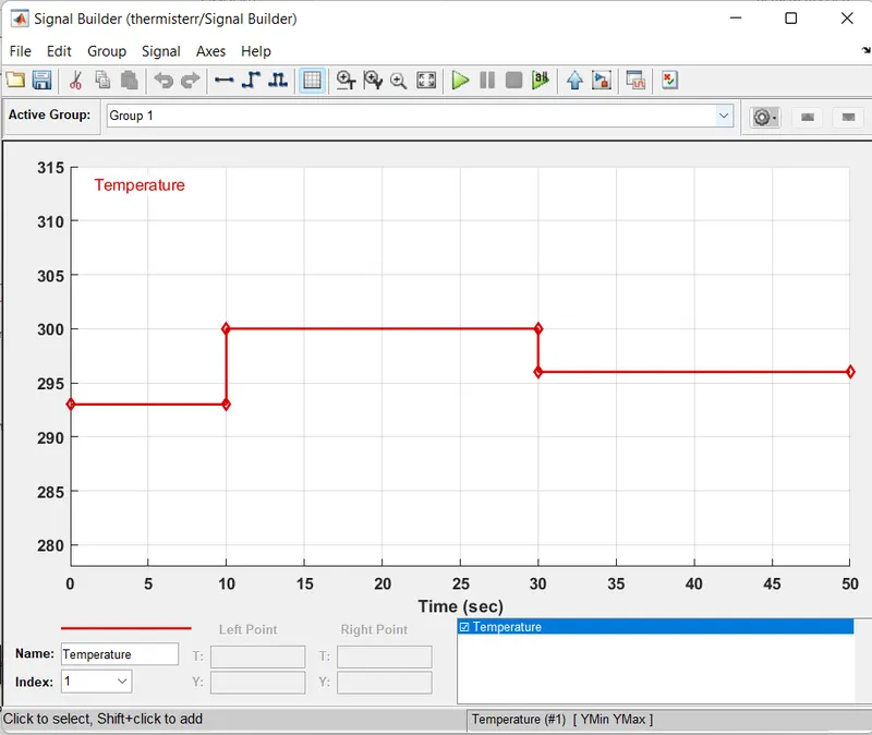
1.Signal builder:-It is used to generate required input signal.
here we have converted all temperatures into kelvin i.e. for 0 to 10 sec=293k, for 10 to 30 sec=300k, for 30 to 50 sec 296k.
2.Controlled temperature source:-The Controlled Temperature Source block represents an ideal source of thermal energy that is powerful enough to maintain specified temperature difference across the source regardless of the heat flow consumed by the system.
3.Thermistor:-It is used to sense the temperature.
4:Battery:-Source of current required to operate circuit.
5.Voltage sensor:-It is used to measure voltage incircuit between two points.
6.Resistor:-Provides opposite nature of current in circuit.
7.Switch:-The Switch block passes through the first input or the third input signal based on the value of the second input. The first and third inputs are data input. The second input is a control input. Specify the condition under which the block passes the first input by using the Criteria for passing first input and Threshold parameters. In this circuit we have threshold to 0.01196
8.Display:-To view the results
9.Scope:-It is used to view the results or plots.
10.Simulink to ps converter:-Convert Simulink input signal into physical signal.
11.Ps to simulink converter:-Convert physical signal into Simulink output signal.
12.Thermal reference:-Reference connection for thermal ports.
13.Electrical reference:-Connection to electrical ground
14.solver configuration:The Solver Configuration block specifies the solver parameters that your model needs before you can begin simulation.
Output:
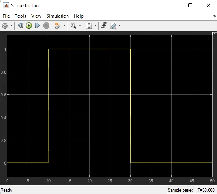
Conclusion: From above results we can understand that at 0 to 10 fan is off at 10 to 30 sec fan is on and at 30 to 50 sec fan is off. That means when temperature raises above 25 degree celcius fan get started.
Refrences: Wikipedia, https://skill-lync.com/knowledgebase/thermistor-challenge