STUDY OF GEAR BOX SLOSHING USING MULTIPHASE MODELLING
1 OBJECTIVE
Perform the numerical Simulation to observe the sloshing effect of lubricating fluid like engine oil & n-heptane (c7h16) at an immersion of 20% & 30% of lubricating fluid. Also comment on error caused during simulation.
2 INTRODUCTION
Performance of any mechanical device heavily depends on type of power losses & intensity of power losses. Gear is a device used for power transmission from input shaft to output shaft. So, the efficiency of gear transmission is becoming a significant concern now a days. Gear suffers from mainly two type of losses. Those losses can be classified as load dependent power losses (due to friction at contact surfaces at bearings & gear) & load independent power losses (churning & windage power losses). Churning power losses is on of the prominent type of losses in the case of load independent power losses. Its effect can be seen significantly at higher speed of gear rotation & higher level of oil fill. Churning losses can be also classified in two parts that are loss caused by rotation of gear to drive the oil & second one is loss caused by the constant suction and extrusion of oil at the contact zone between the engaging gears. It has been experimentally observed that reducing the oil fill level of the gear can reduce the churning losses but at a cost of higher temperature of the gear body. Similarly, increasing the rotational speed will cause in more churning loss. The effect of increasing churning power losses can be seen significantly on transmission efficiency. Also, the consumed energy will be dissipated in the form of heat & will result into increase in temperature of gear. Considering all above aspect, we should provide proper lubrication arrangement, so that gear teeth should get enough oil around tooth spacing for sufficient cooling & for ensuring a good reliability of gear box setup.
Dynamic Meshing is the capacity of Ansys fluent which can handle complex boundary simulation. It is used to mesh those computational grids which changes dynamically during simulation. It is very useful for those flow simulations where geometry changes with respect to time, for example flow around falling objects, internal combustion in cylinder, check valve, store separation. The 3 main component of dynamic meshing are smoothing methods, dynamic layering, and local remeshing methods. These components can tackle most of the challenging problem. Layering scheme is sufficient for a simple dynamic problem which involves only linear boundary motion.
Fluid Sloshing Effects
The oscillatory motion experienced by free surface of liquid inside its container is known as fluid sloshing effect. It comes into picture when a partially filled liquid container undergoes any disturbance. The nature of motion experienced by liquid depends on type of disturbance, shape of container, etc. It may result into motion like planar, non-planar, rotational, irregular beating, symmetric, asymmetric, quasiperiodic and chaotic.
When the gear box is forced to move, free surface undergoes a large amount of deformation resulting in large amplitude of fluid. It will result into an impact pressure on inner surface may damage it if amplitude is high. Sloshing may cause high local pressure & large total force. Sloshing may cause a broad variety of problem wrt safety importance. It will affect adversely when gearbox may start vibrating at a frequency of same as the vibration frequency of liquid. It is the condition of resonance & if there is no damping then movement in the gearbox becomes highly magnified. It will result in non linear characteristics of motion which is extremely tough for doing theoretical analysis and numerical calculation.
3 GEOMETRY & MESHING
3.1 GEOMETRY
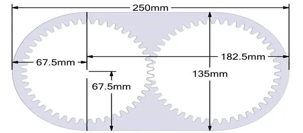
We have extracted fluid volume from 3d model & simulation was done on only 2d model. It helps in saving our time of numerical simulation & it also reduces computational cost. Following diagram shows a detailed sketch of 2d gear model with detailed dimension. The radius of gear is 67.5mm & width of gear box is 250mm.
3.2 MESHING
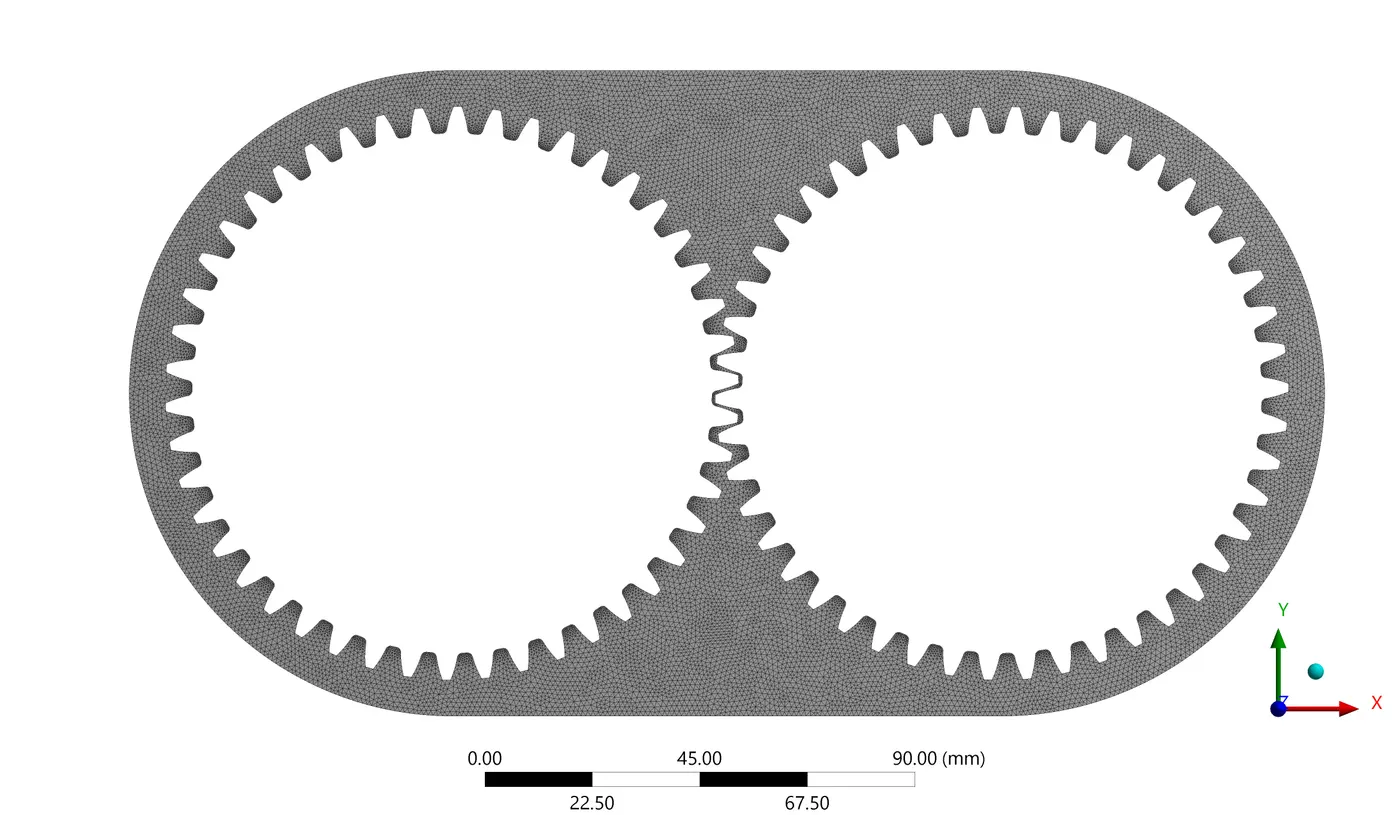
All triangle method of meshing was chosen to discretise the 2D model into finite volume. The element size was 1mm. It resulted into 15968 nodes & 28513 elements. Dynamic method of meshing was chosen to handle the motion of geometry. It has been already explained in introduction section. Dynamic meshing is a technology to reconstruct the mesh around the gears.
4 PHYSICS & SETUP
Volume of fluid method has been chosen to observe the sloshing effect of lubricating fluid. Deformation of fluid causes very high strain rate of fluid present between the tooth in mesh. VOF is very suitable & capable of capturing these effects. Laminar effect has been observed only for this study. Transient study has been performed to study the sloshing effect. Time step size was 0.0001. Simulation was done for at least 0.06 second to ensure at least 2 rotation of gear.
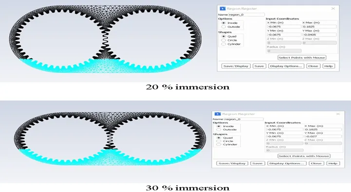
Above figure shows the gear box immersed in 20% & 30% of lubricating fluid. Fluid were also changed to observe the viscosity effect. So, total of 4 different cases has been taken in observation.
4.2 UDF
It is user defined function used to apply the boundary condition using code. It can be compiled using VS CODE. We have to only operate Ansys with help of vs code & after uploading UDF it automatically applies the boundary condition. Following UDF code was used to apply angular & linear velocity of left and right gear.
#include "udf.h"

DEFINE_CG_MOTION(right_motion, dt, vel, omega, time, dtime)
{
	vel[0] = 0.0;
	vel[1] = 0.0;
	vel[2] = 0.0;

	omega[0] = 0.0;
	omega[1] = 0.0;
	omega[2] = 2.0e2; /* [rad/s]*/
}
DEFINE_CG_MOTION(left_motion, dt, vel, omega, time, dtime)
{
	vel[0] = 0.0;
	vel[1] = 0.0;
	vel[2] = 0.0;

	omega[0] = 0.0;
	omega[1] = 0.0;
	omega[2] = -2.0e2; /* [rad/s]*/
}
4.3 LUBRICATION DISTRIBUTION AROUND GEAR TOOTH
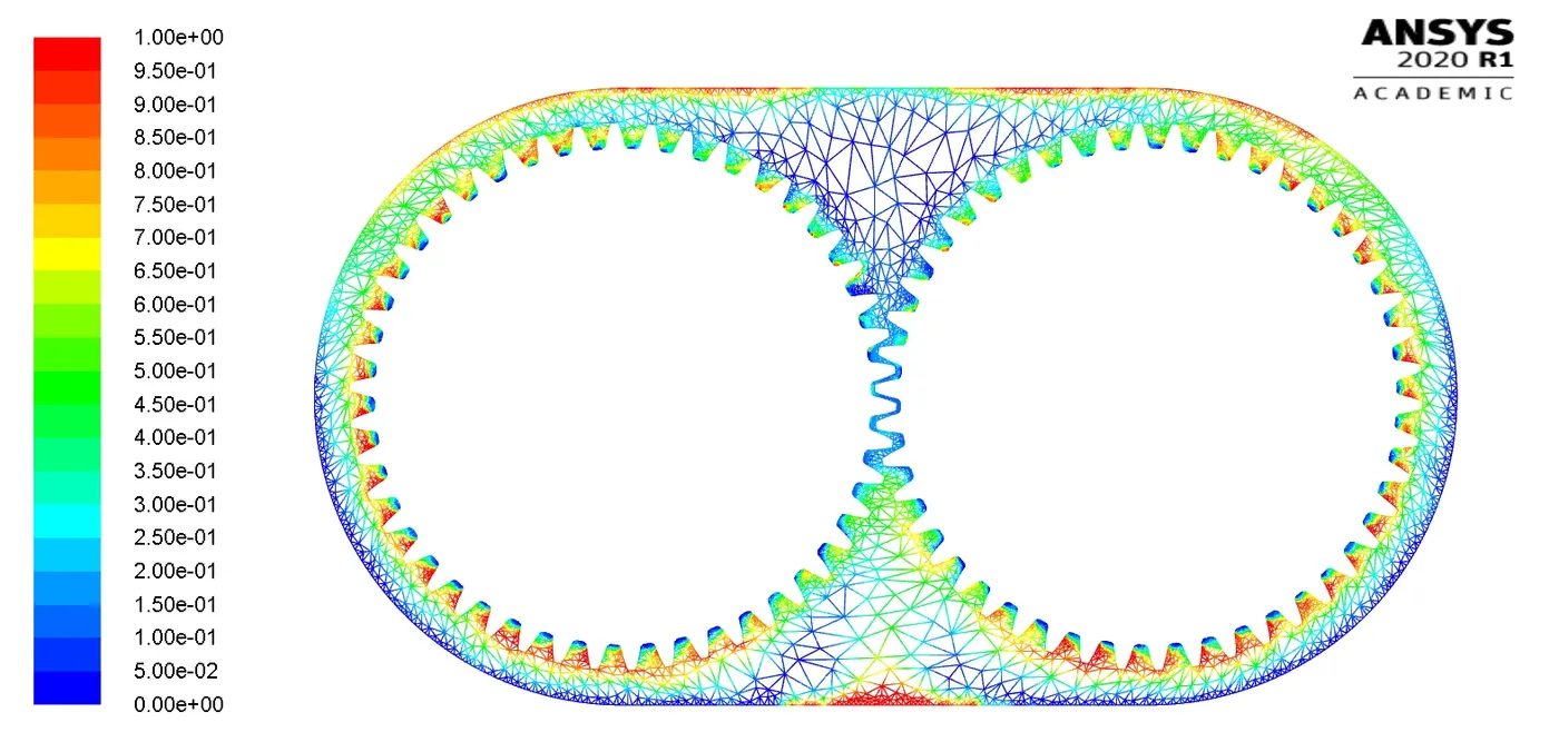
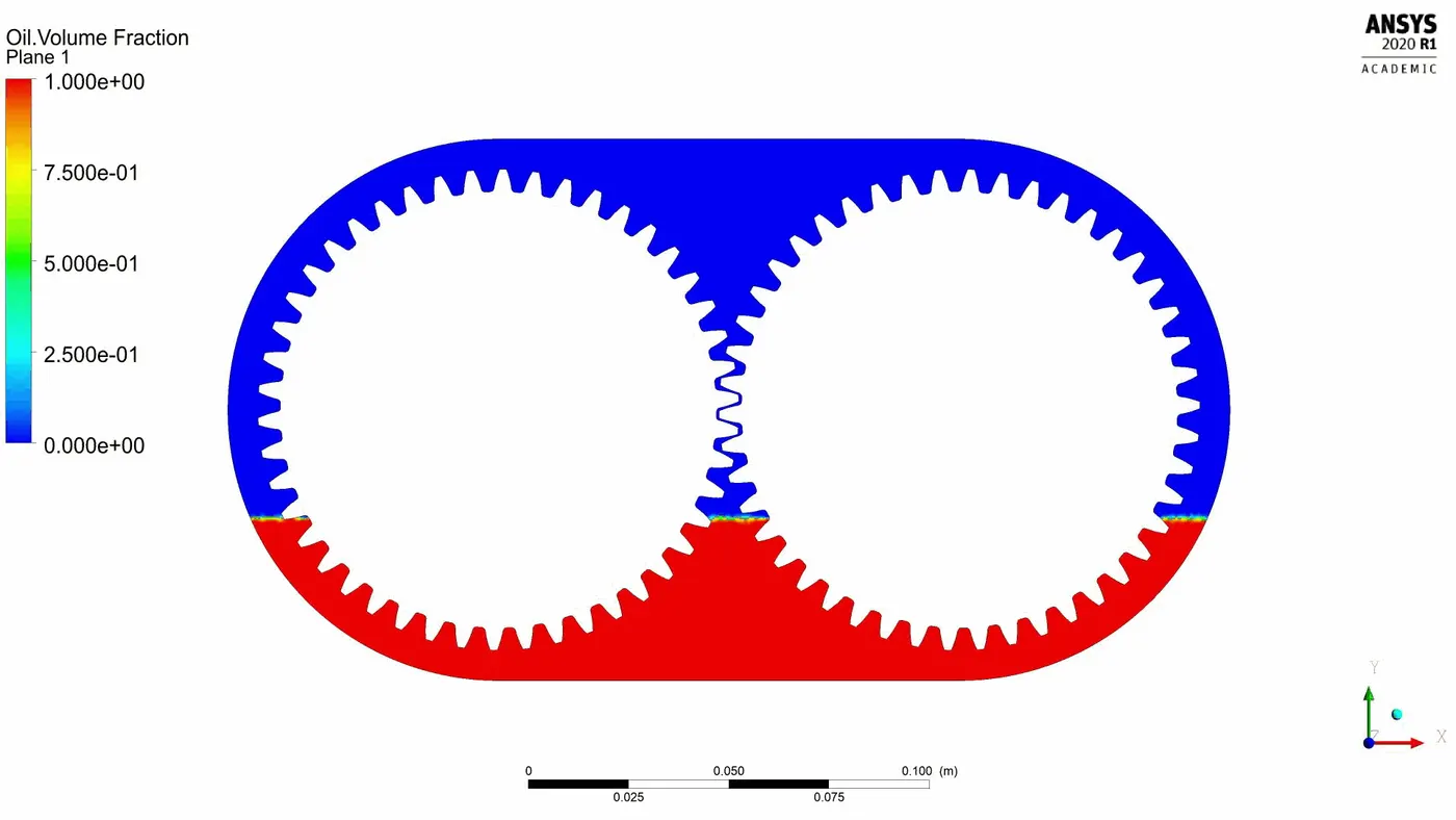
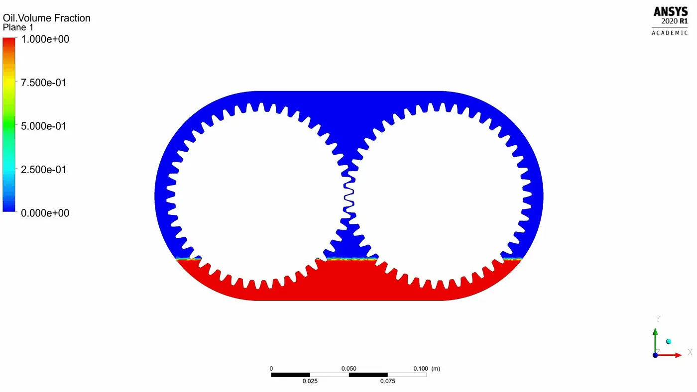
Figure below shows the distribution of lubrication wrt time. Comparison of fluid at 20% & 30% immersion has been done. At initial time (t=0) there is no deformation in fluid & the level of fluid in lower tank is higher which can be seen clearly. Distribution of lubrication can be seen more uniformly at 30% of immersion. Further if flow from time 0.0177 sec to 0.0197 sec tell us that due to negative pressure at tooth meshing zone it sucks the lubrication present just below tooth (meshing zone).
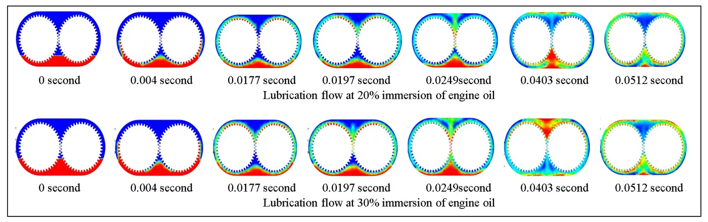
As flow proceed wrt time, better lubrication of tooth can be seen. Higher the immersion zone, better lubrication can result in better heat dissipation.
4.4 STRAIN RATE
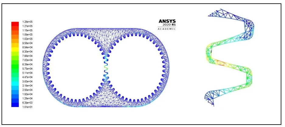
Below figure shows the magnified zone where strain rate is high. It occurs at tooth in complete mesh. For all the four cases same nature was found with different magnitude.
4.5 PRESSURE DISTRIBUTION
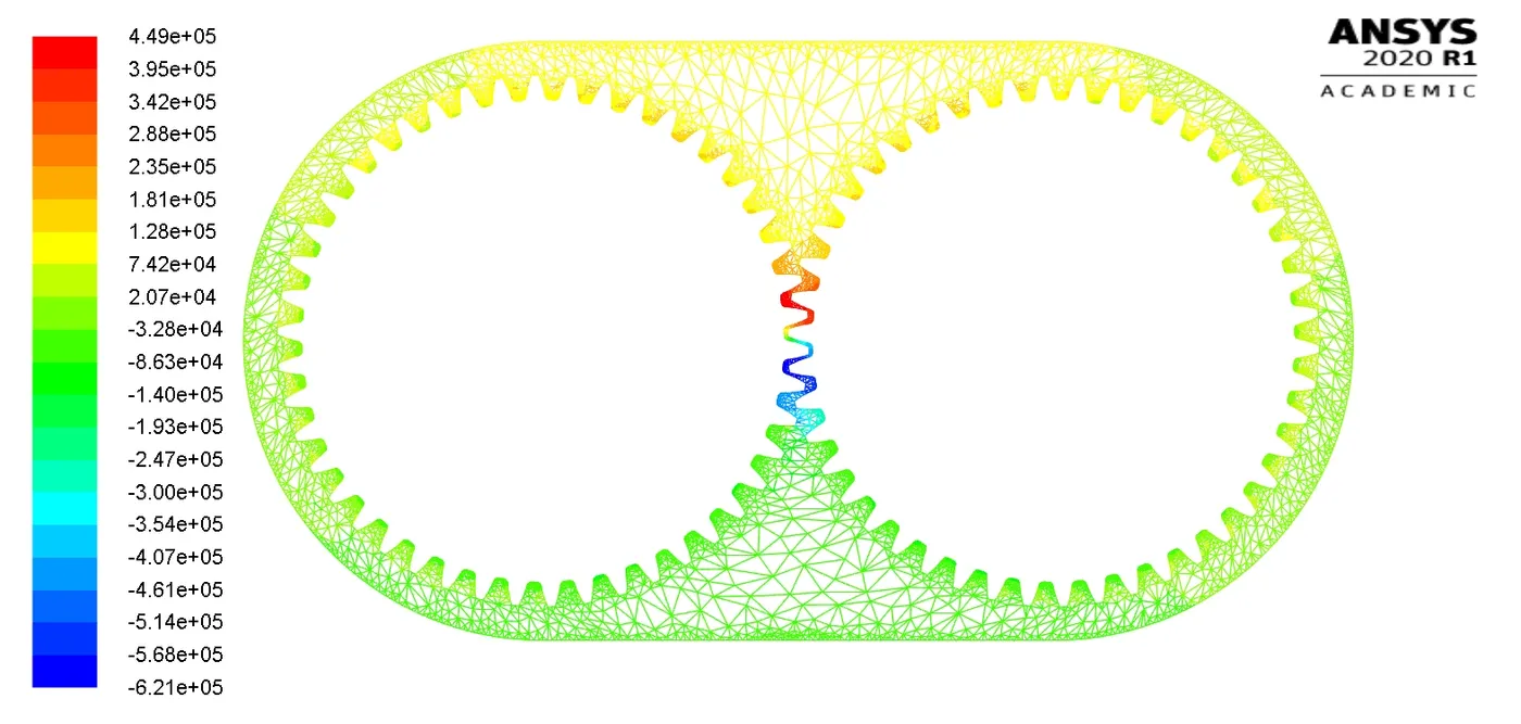
Figure below shows (20% immersion of engine oil) the counter of pressure. At tooth meshing there is negative pressure which can be seen clearly by blue colour. It helps in better lubrication of tooth in mesh & allows a smooth operation. Pattern is similar in all 4 cases.
4.6 VOLUME FRACTION - 20% engine oil
We can see clearly the distribution of engine oil around gear tooth.
5 FLOW SIMULATION
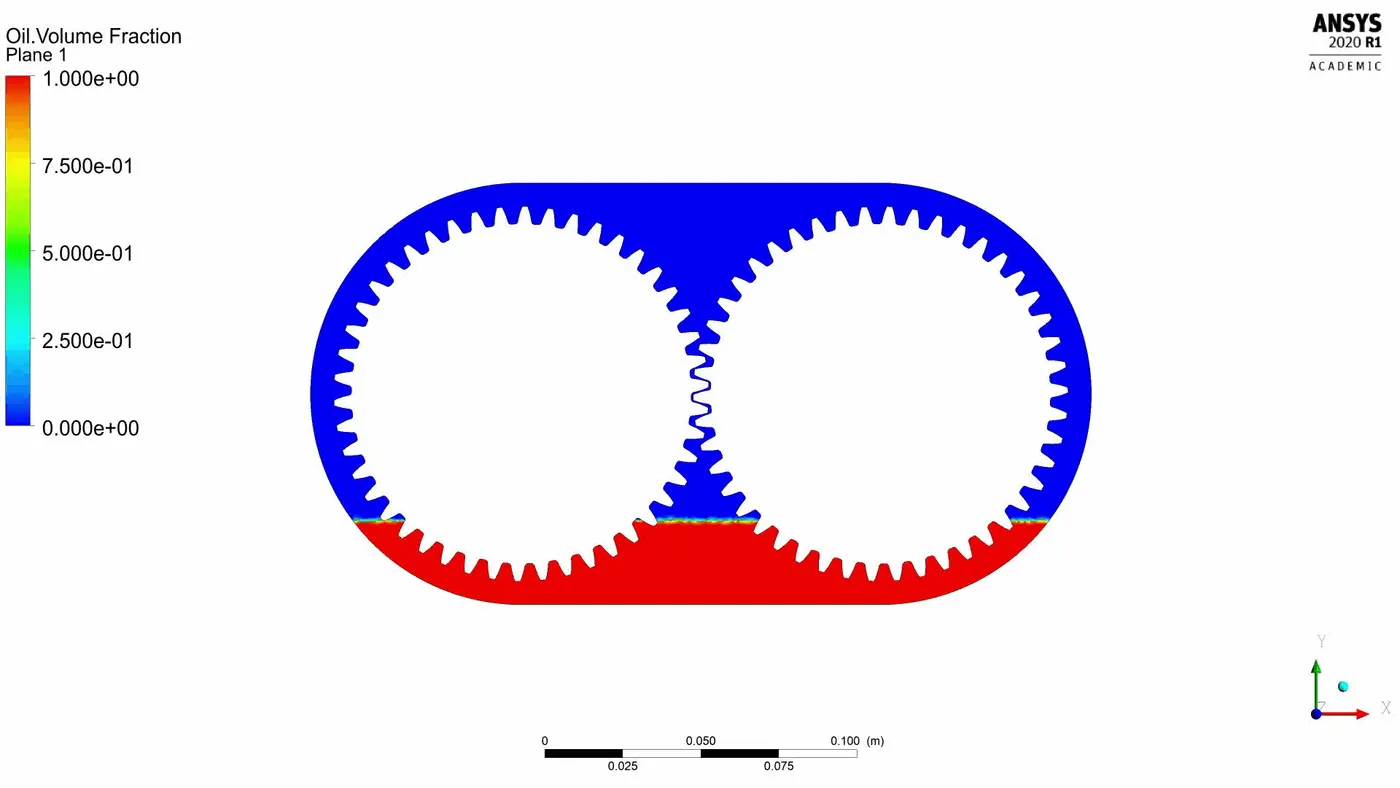
5.1 VOLUME FRACTION - 20% engine oil
We can see clearly the distribution of engine oil around gear tooth.
5.2 VOLUME FRACTION-30% ENGINE OIL
5.3 20% N HEPTANE
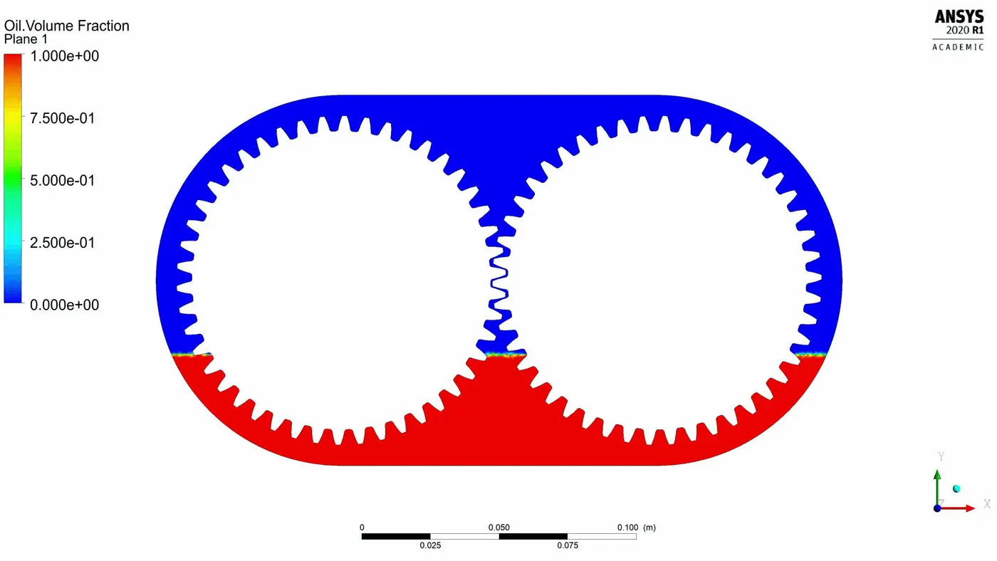
5.4 30% N HEPTANE
6 CONCLUSION
6.1 PARRAMETER AFFECTING POWER LOSS
Rotational speed, viscosity of fluid, oil tank level is the main parameter which affect the power losses. Also, the orientation of gear box influences the lubrication effect. In present study we have observed the effect of oil viscosity & fuel tank level. The focus was to find out parameter which influence churning losses.
6.2 ERROR IN SIMULATION
6.2.1 Dynamic mesh failed
It is the result of bad element quality, using a greater number of processers, using large time step size. Any one of the reasons mentioned above mat be reason behind it & it don’t allow Ansys to mesh any element other than triangular shape. Always using triangular element shape in dynamic zone, appropriate smoothing parameter, can be feasible solution to avoid this error. Also, time step size must be less than the mesh size in dynamic zone.
6.2.2 Negative cell volume detected
This error is encountered if there exist a huge distortion in element shape. There is a huge scope of modification in vertex, or edges, to penetrate a opposite face resulting in a negative volume. It generates unphysical behaviour of equation. It may be result of large time step size wrt displacement of your mesh displacement.
It can be eliminated by decreasing time step size or setting up dynamic remeshing properly. Element size must be small. Sometimes using only 1 processor will eliminate this error.