Project 5
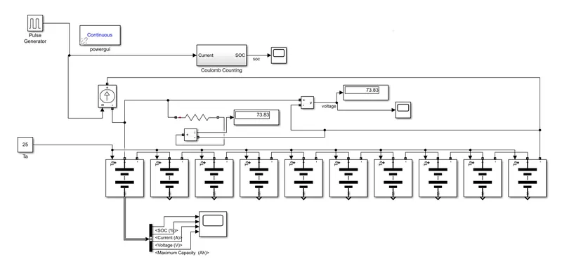
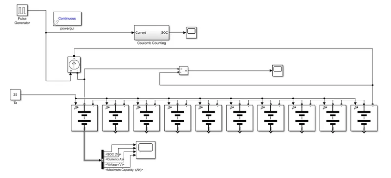
AIM:For a 10 cell series, calculate the voltage, current and SOC. Also simulate the aging and thermal effects at different charge and discharge rates. Comment on the battery pack’s capacity.
Block used: Pulse generator,Power gui,controlled current source,battery ,constant,bus selector ,voltage measurement,and Coulomb counting subsytem
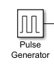
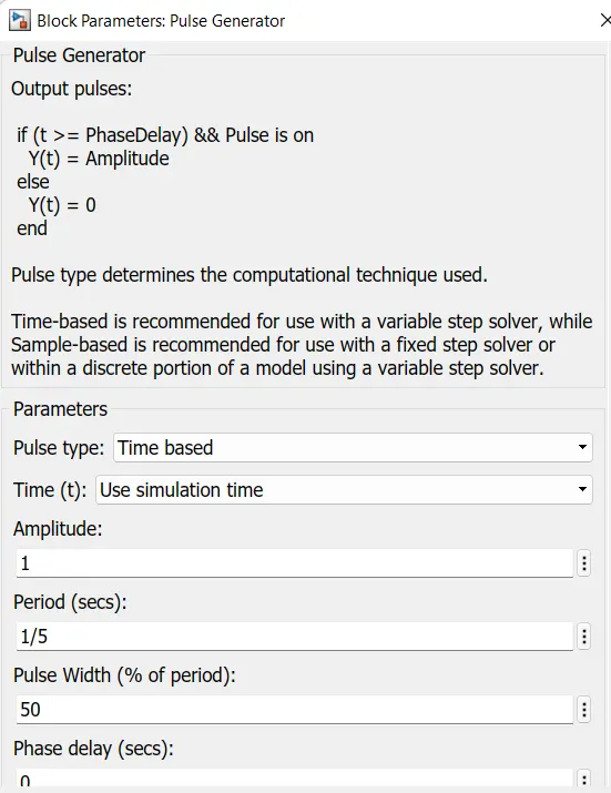
Pulse generator:
Pulse genertor generates pulses according to given parameter.
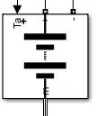
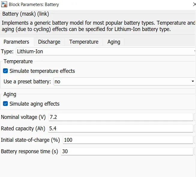
Battery
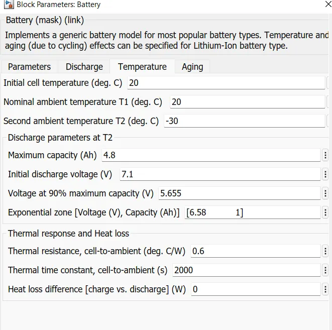
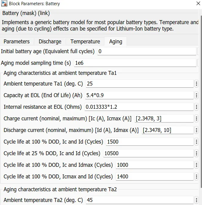
Here we use 10 battery .with nominal voltage 7.2 and rated capacity 5.4Ah we selected simulating temperature and aging effect simulation
Controlled current source
The Controlled Current Source block represents an ideal current source that is powerful enough to maintain the specified current through it regardless of the voltage across the source.
The output current is I = Is, where Is is the numerical value presented at the physical signal port.The positive direction of the current flow is indicated by the arrow.

Constant block
This block generate a constant value
we set constant value 25 for ambient temperature

Voltage measurement
This block measure voltahe across terminals

Bus selector
This block accepts a bus as input which can be created from a Bus Creator, Bus Selector or a block that defines its output using a bus object. The left listbox shows the elements in the input bus. Use the Select button to select the output elements. The right listbox shows the selections. Use the Up, Down, or Remove button to reorder the selections. Check 'Output as virtual bus' to output a single bus.

Scope
The scope block display signals generated during simulation.

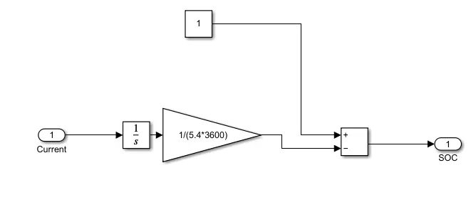
Coulomb counting subsytem
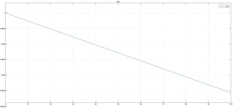
- Battery is discharging as time increases
- Initially battery is fully charged and battery got discharged with time and 99% battery is remaining
- At some portions of the plot we can see increase in soc value because direction change of controlled current source battery get charged.so soc increses
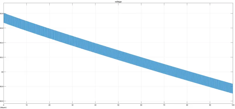
- Battery pack voltage decreses with increse in time its go up for directionchange of current source output
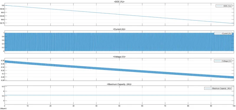
- SOC decreases with increasing time
- current follows the controlled current source value given by a pulse generator
- voltage decreases with increase in time
- we got maximum capacity of battery 5.58Ah