Project
Aim:
To design a system level simulation of an all-terrain-vehicle(ATV) using Continuous variable transmission(CVT).
Analysis:
ATV is an one seater vehicle having four wheels designed for the off road travel. ATV with CVT has advantages over other transmssion such as improved fuel efficiency. CVT has four maor parts such as primary pully, variator, secondary pully and belt. CVT provides unending range of gear ratio while you drive. CVT maintains constant angular velocity regardless of output speed. It is also called single speed, shiftless and steepless transmission.
Case1 - ATV with CVT without dashboard
For this system brake and throttle inputs are given via signal buider. The gear ratio input to the CVT subsystem is also provided via signal builder. CVT subsystem has two rotational motion sensor to measure the motion of the shaft and it has variable gear ratio box which provide gear ratio to the two shafts. Respective model and output plot for the case1 is as shown below.
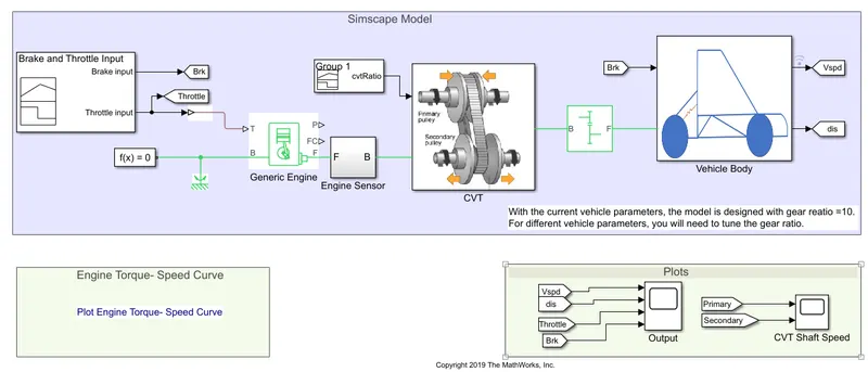
Fig.1 Simulink model of ATV without dashboard
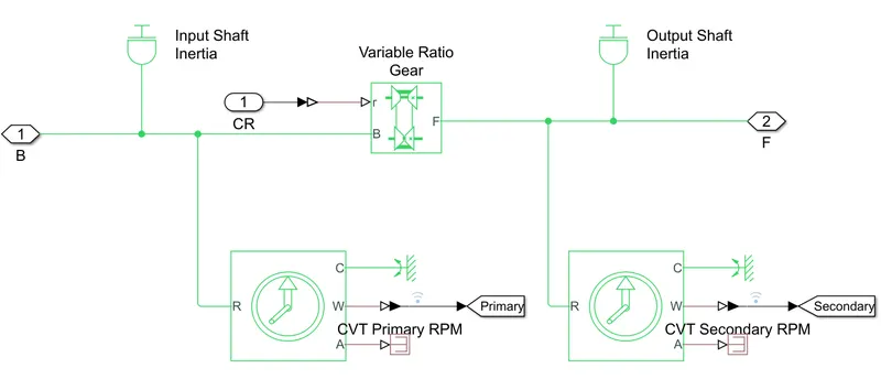
Fig.2 Configuration of CVT subsystem
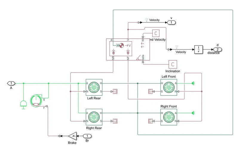
Fig.3 Configuration of vehicle body subsystem
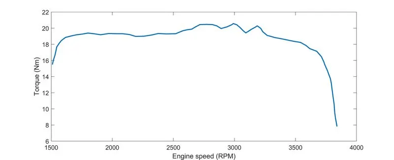
Fig.4 Speed vs torqe characteristic
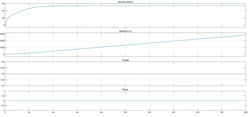
Fig.5 Plot of velocity, throttle and brake
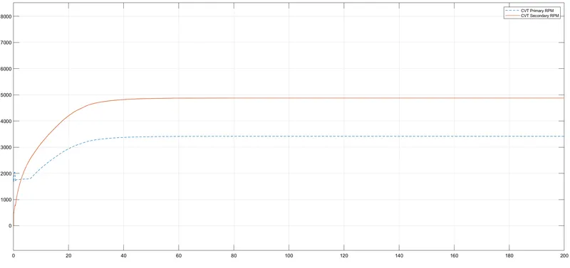
Fig.6 Plot of motion of primary and seconday shaft
Here, brake input to the system is maintained as zero and throttle input is 0.5. We can observe the increase in the velocity initially and then it is constant as throttle is constant. Rotational speed of the secondary shaft is more than the primary shaft because radius of the secondary shaft is large.
Case2 - ATV with CVT with dashboard
Dashboard is used as input to the system to control brake and throttle. CVT and Vehicle body subsystems looks similar to the previous model. Respective model and output plot for the case2 is as shown below.
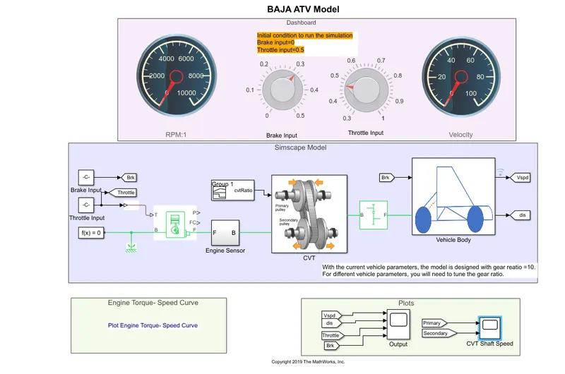
Fig.7 Simulink model of ATV with dashboard
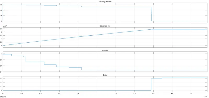
Fig.8 Plot of velocity, throttle and brake
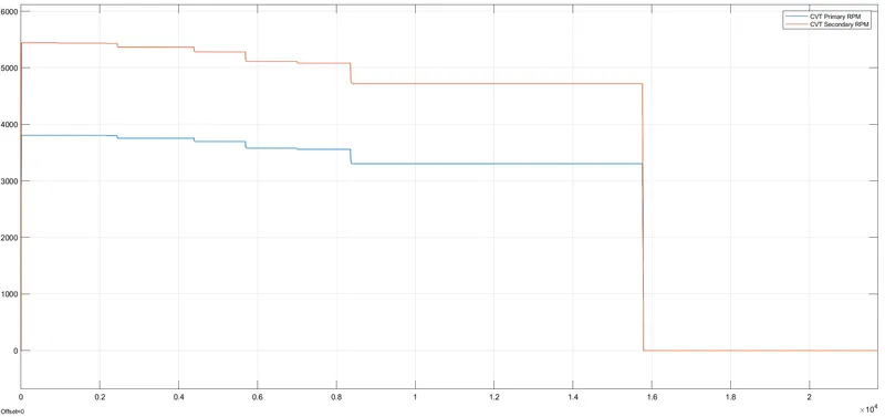
Fig.9 Plot of motion of primary and seconday shaft
Here, Brake and throttle can be vary according to our requirement. Initially barke is maintained at zero. Velocity starts decrease as the application of the throttle. Velocity becomes zero as the application of the brake maintaining throttle constant. Rotational speed of primary and secondary shafts are initially high. It reaches zero as the application of the brake.
Case3 - ATV with CVT without dashboard using lookup table
Brake and throttle inputs are applied using signal generator or basic function block. The gear ratio input to the CVT subsystem is provided via lookup table. Model looks like closed loop. Vehicle speed generated at the output of the system is taken as input to CVT subsystem as lookup table uses this data to generate required gear ratio. Vehicle body subsystem looks similar to previous model. In CVT subsystem, we can observe 1D-looksup table block. Respective model and output plot for the case3 is as shown below.
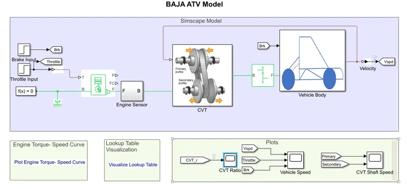
Fig.10 Closed loop Simulink model of ATV without dashboard
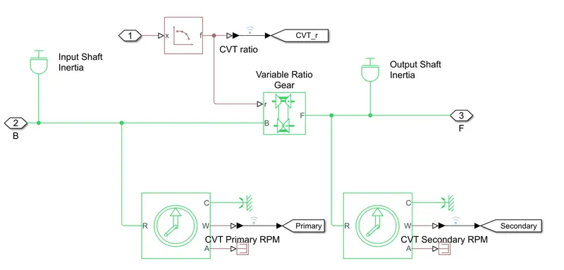
Fig.11 Configuration of CVT subsystem
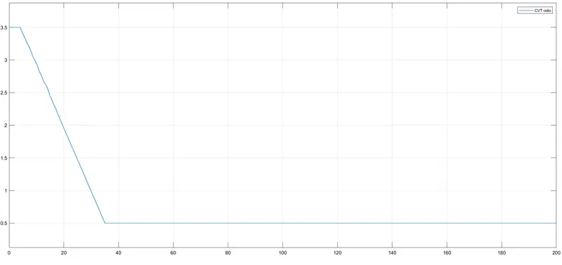
Fig.12 Visualization of CVT ratio given to the system
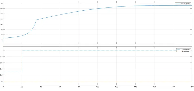
Fig.13 Plot of Velocity, throttle and brake
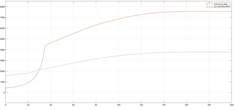
Fig.14 Plot of motion of primary and seconday shaft
Here, Brake input is maintatined at zero state. Throttle input initially 0.3, then it increases to 1 at 20s. We can oberve increase in the velocity as throttle increases. Rotational speed of the secondary shaft is more than the primary shaft. But, we can observe little disturbance in the inital stage because of the lookup table input.
Case4 - ATV with CVT with dashboard using lookup table
Dashboard is used as input to the system to control brake and throttle. Gear ratio is applied using lookup table similar to previous model. Respective model and output plot for the case4 is as shown below.
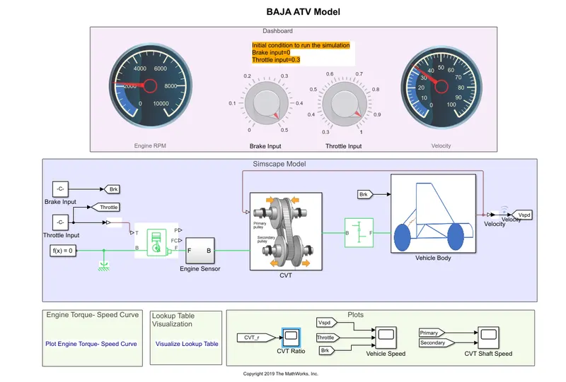
Fig.16 Closed loop Simulink model of ATV with dashboard
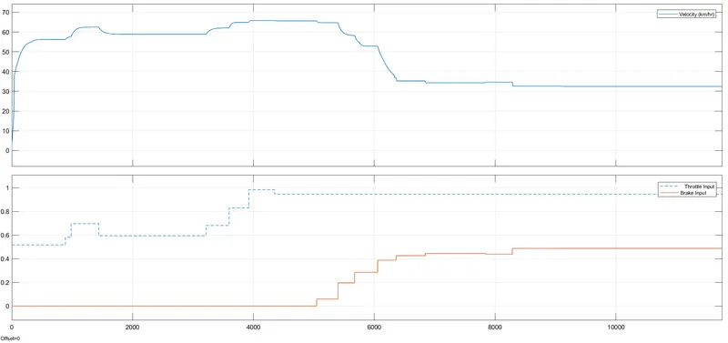
Fig.17 Plot of velocity, brake and throttle
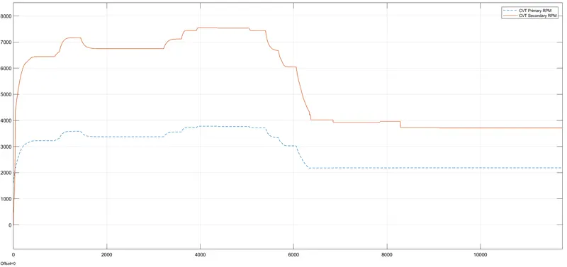
Fig.18 Plot of motion of primary and seconday shaft
Here, Brake and throttle can be vary according to our requirement. Initially barke is maintained at zero. Velocity starts decrease as the application of the throttle. If throttle increse, velocity also increases. Velocity decreases as the application of the brake maintaining throttle constant. As we apply throttle, rotational speed of primary and secondary shafts increases. It decreases as the application of the brake.
Result:
System level simulation of ATV has been analyzed successfully. Application of brake and throttle affects to velocity of the vehicle as well as rotational speed of shaft. Application of brake reduces both velocity and rotational speed of shaft. As throttle increses, velocity and shaft speed increses. Performance of closed loop system is better than the open loop system.