Project
AIM-Carry out a system-level simulation of an all-terrain vehicle.
A CVT transmission, or continuously variable transmission, seamlessly changes through an unending range of effective gear ratios while you drive, whereas other kinds of mechanical transmissions offer a fixed number of gear ratios and have hard shifts between each.
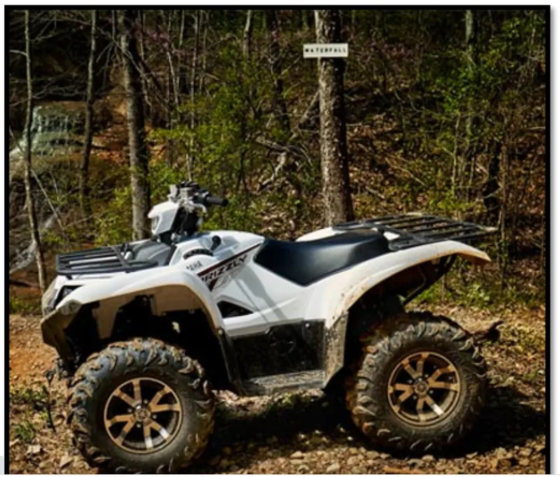
A CVT, or continuously variable transmission, seamlessly changes through an unending range of effective gear ratios while you drive, whereas other kinds of mechanical transmissions offer a fixed number of gear ratios and have hard shifts between each as explained by Certified Transmission Repair. CVT transmission systems are also known as single-speed, shiftless, and stepless transmissions.
The shiftless nature of a CVT offers unparalleled flexibility that maintains constant angular velocity regardless of output speed. Additionally, a continuously variable transmission makes accelerating smooth and offers enhanced fuel economy
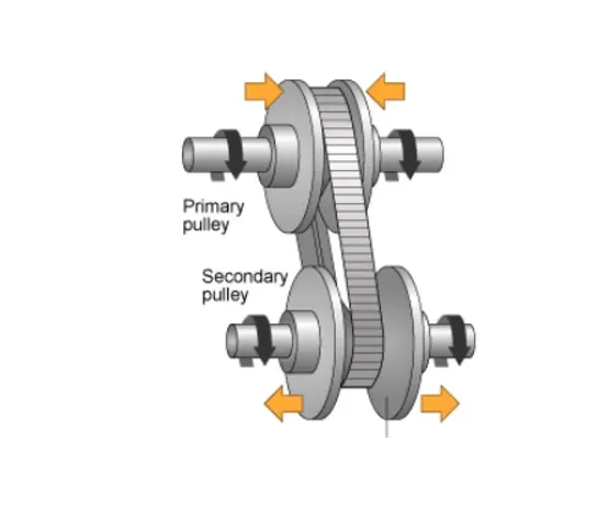
Working
While a traditional transmission uses a wide variety of intricate parts to shift between a range of preset gears, most CVT systems work through a pulley system. In short, this system consists of cones at each pulley connected via a chain belt. The cones can move to increase or decrease the belt diameter to change gear ratios, allow for quick shifting into the needed ratio for increased power, and boost fuel economy.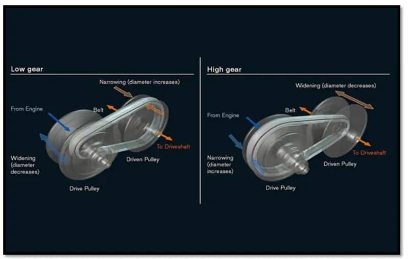
One pulley in the CVT is connected to the engine and the other directs power to the wheels. The width of these pulleys changes based on the needed power; as one gets larger, the other gets smaller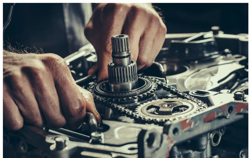
CASE1-CVT MODEL
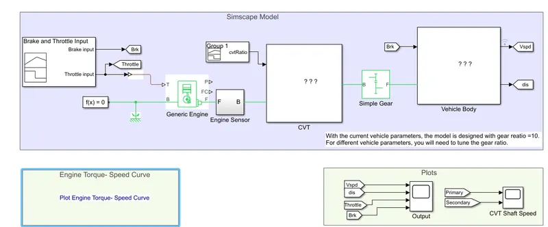
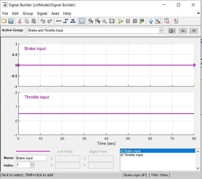
Here we have given brake input manually to 0 and throttle input to 0.5
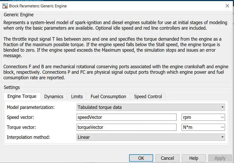
ENGINE
Represent a system level model of spark-ignition and diesel engine suitable for use at initial stages of modelling when only the basic parameters available.Optional idle speed and red line controllers are included.The throttle input signal T lies between 0 and 1 and specify the torque demanded from the engine as a fraction of the maximum possible torque.
connection F and B are mechanical rotational conserving ports associated with the engine crankshaft and engine block respectively,connections p and fc are physical signal output ports through which engine power and fuel consumption rate are reported.
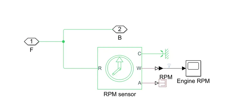
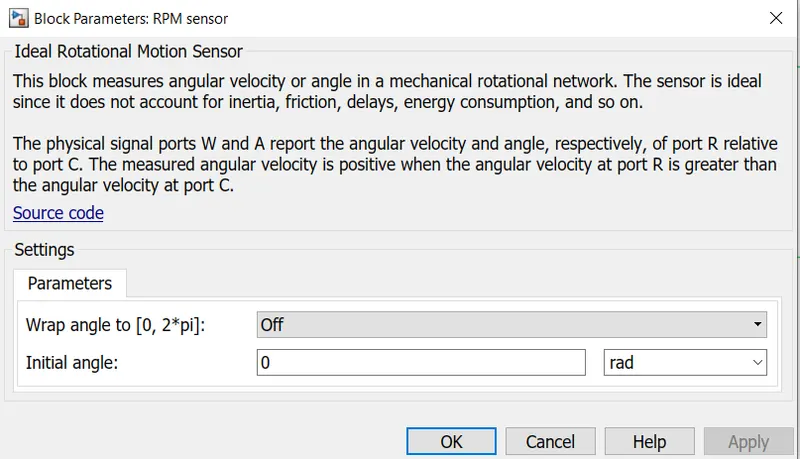
This block measures angular velocity or angle in a mechanical rotational network. The sensor is ideal since it does not account for inertia, friction, delays, energy consumption, and so on.The physical signal ports W and A report the angular velocity and angle, respectively, of port R relative to port C. The measured angular velocity is positive when the angular velocity at port R is greater than the angular velocity at port C.
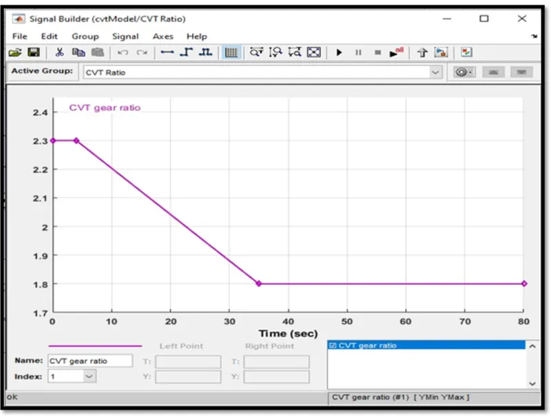
The CVT (Continuously Variable Transmission) provides smooth and "stepless" ratio changes, unlike conventional transmission systems that use sets of fixed gears.
The CVT is an automatic transmission that uses two pulleys with a steel belt running between them. To continuously vary its gear ratios, the CVT simultaneously adjusts the diameter of the "drive pulley" that transmits torque from the engine and the "driven pulley" that transfers torque to the wheels. With stepless shifting of gear ratios, the CVT can avoid the shift-shock and deliver smooth driving, making it an exceptional transmission solution.
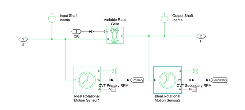
variable transmission ratio
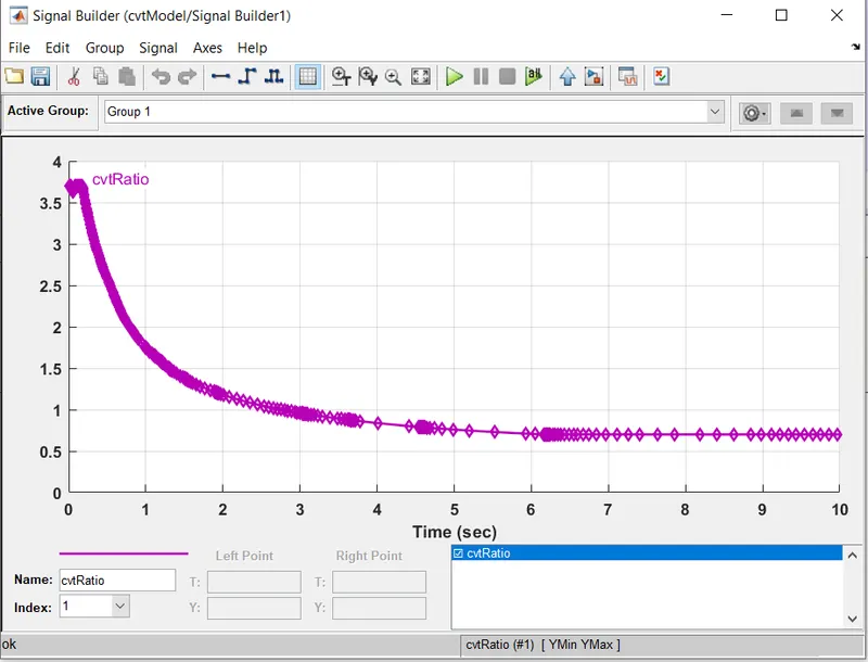
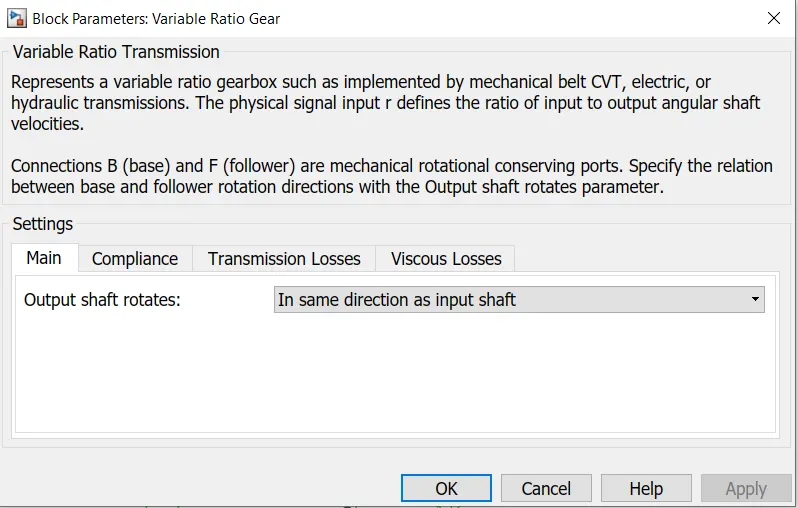
Represents a variable ratio gearbox such as implemented by mechanical belt CVT,electric, or hydraulic transmission.The physical signal input defines the ratio of input to output angular shaft velocities,connections B and F are mechanical rotational conserving ports.specify the relation between base and follower rotation directions with the output shaft rotates parameter.
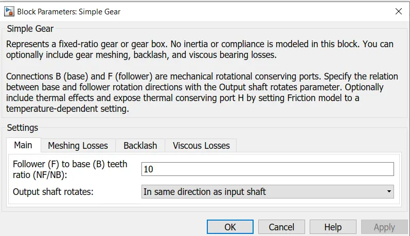
Represents a fixed-ratio gear or gear box. No inertia or compliance is modeled in this block. You can optionally include gear meshing, backlash, and viscous bearing losses.Connections B (base) and F (follower) are mechanical rotational conserving ports. Specify the relation between base and follower rotation directions with the Output shaft rotates parameter. Optionally include thermal effects and expose thermal conserving port H by setting Friction model to a temperature-dependent setting.
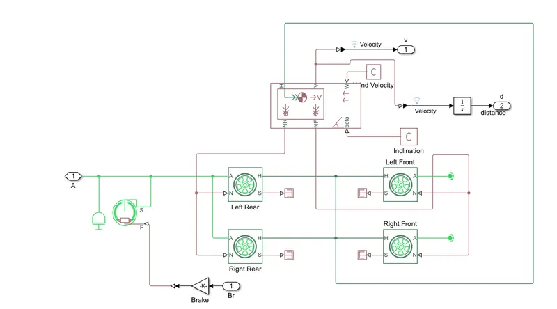
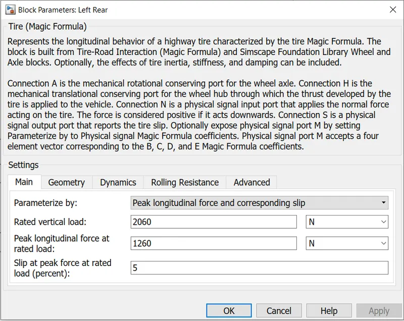
Represents the longitudinal behavior of a highway tire characterized by the tire Magic Formula. The block is built from Tire-Road Interaction (Magic Formula) and Simscape Foundation Library Wheel and Axle blocks. Optionally, the effects of tire inertia, stiffness, and damping can be included.Connection A is the mechanical rotational conserving port for the wheel axle. Connection H is the mechanical translational conserving port for the wheel hub through which the thrust developed by the tire is applied to the vehicle. Connection N is a physical signal input port that applies the normal force acting on the tire. The force is considered positive if it acts downwards. Connection S is a physical signal output port that reports the tire slip. Optionally expose physical signal port M by setting Parameterize by to Physical signal Magic Formula coefficients. Physical signal port M accepts a four element vector corresponding to the B, C, D, and E Magic Formula coefficients.
same as left front and right front.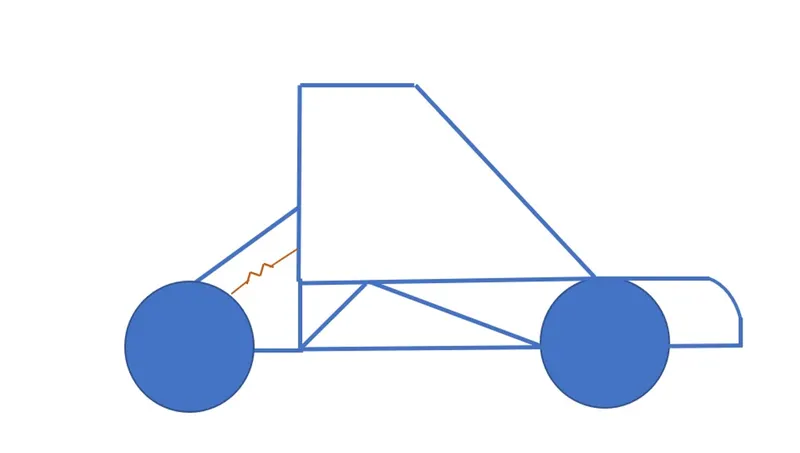
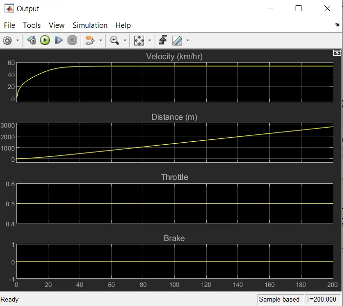
as running the model for 200 sec keeping brake 0 and throttling 0.5 with distance increasing from 0 to 300 mtr in 200 sec after 30sec velocity remain constant for 55km/hr.
 .
.
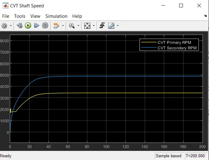
here model is run for 200 sec in which primary rpm start from 2000 then down below 2000 after 5 sec it reaches 2000 then after 5 sec it increaes above 2000 and increases till 30 sec then remain constant above 3000 and below 4000.
in secondry cvt rpm start from 0 and uniformly increases till 30 sec and remain constant after 30sec to 4900 rpm.
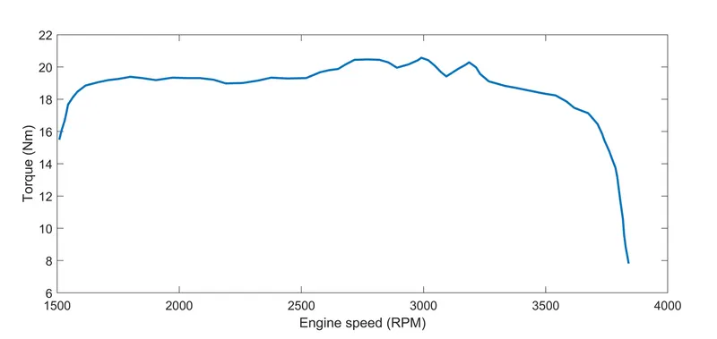
With the current vehicle parameters, the model is designed with gear reatio =10.
For different vehicle parameters, you will need to tune the gear ratio.
CASE-2 CVT MODEL WITH DASHBOARD
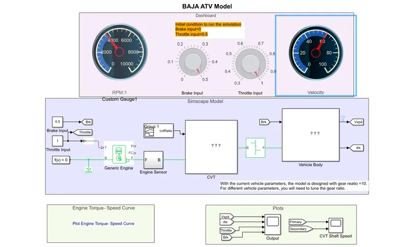
Rest full model is same here we are are using knob gauge for rpm velocity brake throttle.
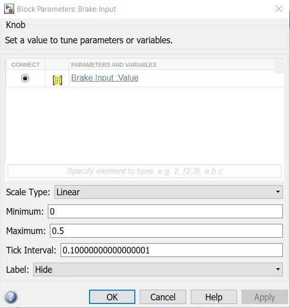
initial condition brake=0,throttle =0.5.
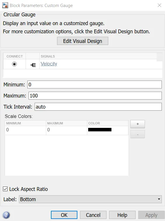
guage used to display .
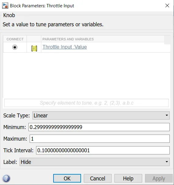
throttle to 0.5 to 1.
comparing output
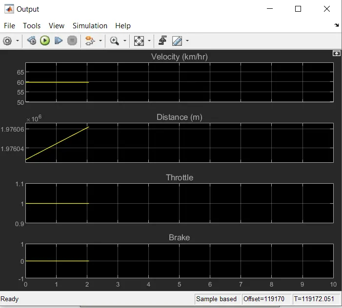
when we run model for infinity brake=0 throttle =0.5 to 1 and distance increases and velocity =59 km/hr
constant from starting.
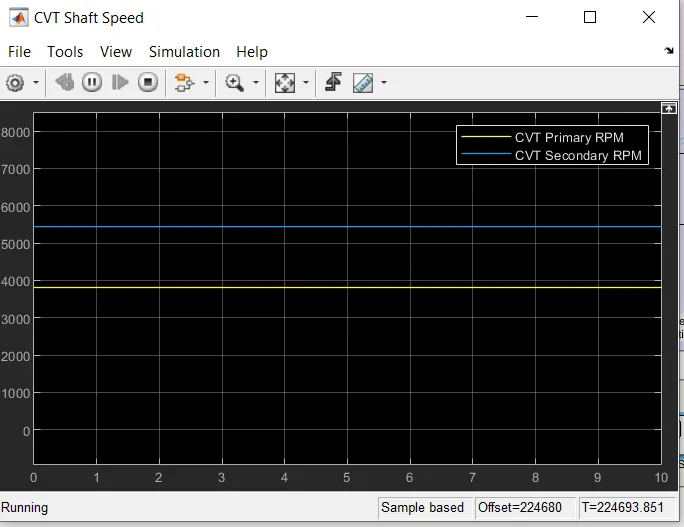
here for running to infinite time first primary rpm starts from 2000 and remain constant at 4000.but secondary rpm varies from 0 and constant for 5500.
CONCLUSSION
IN this model we have a dashboard which contains knobs to control the inputs,in this case,the inputs throttle and brake are not provided using signal builder. a knob is provided to control both the parameters in real time for the users.