Project
Aim :
To prepare a technical report of simulation of BAJAJ All Terrain vehicle (ATV) Using Different Conditions.
Tasks :
Carry out a system-level simulation of an all-terrain vehicle & Prepare a technical report explaining the model properties & comments on the results.
- To do a system-level simulation of All-Terrain vehicle
- To study the performance or the behaviour of different CVT Models given and do the detailed report of results.
Continuosly variable transmission(CVT):-
A continuosly variable transmission(CVT)is anautomatic transmission that can change seamlessly through a continuos range of gear ratio.this contract with another transmission that provide a limited number of gear ratio with fixed step.the flexibility of a CVT with suitable control may allow the engine to oparate at the constant RPM while the vehicle moves at varying speed
BAJA ATV Models:
- BAJA_cvtModel
- BAJA_cvtModel_Dashboard
- BAJA_cvtModel_data
- BAJA_cvtModel_dashboard_mapped/CV
BAJA ATV CVT Model:(SINGLE LOOP)
Signal Builder Block:
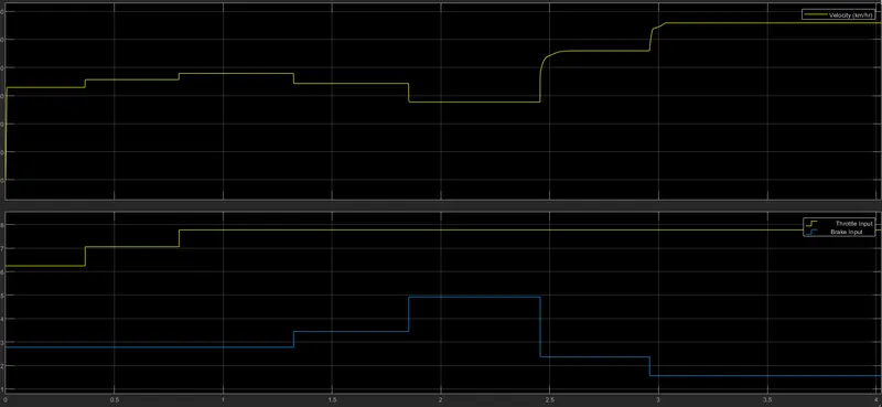
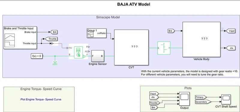
Using this block the brake input signal =0 and the throttle input values 0.5 respectively provided to the engine block. Throttle input will control the fuel consumption by the engine such that torque-speed input data is provided to the engine. So The required value of torque at a defined speed is produced by the engine with a sufficient amount of fuel consumption.

- No brake is provided
- A constant throttle of 0.3 for the first 20 seconds, and full throttle of 1 for the remaining
- These two parameters are fed into the engine
Generic engine:
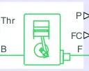
- The engine uses a programmed relationship between speed and torque, modulated by the throttle signal. The throttle input is seen above (fed into port T) and the speed-torque data points are extracted from the graph shown below and fed into the engine through creation of column vectors in MATLAB.
- Crankshaft (Port F) is connected to an engine sensor, which simply senses the angular velocity and angular displacement of the crankshaft.
- The simple gear between engine and the CVT gear box is to slow down the engine RPM (in case it is too high) before it is fed to the CVT. An appropriate gear ratio needs to be selected so that over or under-revving isn't an issue.
Engine sensor Block:
This block measures angular velocity or angle in a mechanical rotational network. The physical signal ports W and A report the angular velocity and angle, respectively, of port R relative to port C. The measured angular velocity is positive when the angular velocity at port R is greater than the angular velocity at port C.
Continuously varying transmission gear CVT:
It represents a variable ratio gearbox, which implements a push bolt continuously variable transmission(CVT) with independent radii control, we can use this block for control system design, powertrain matching, and fuel economy studies. The physical signal input r defines the ratio of input to output angular shaft velocities. Connections B(base) and F(follower) are mechanical rotational conserving ports. The input and output shafts rotate in the same direction. No transmission and viscous losses are considered.
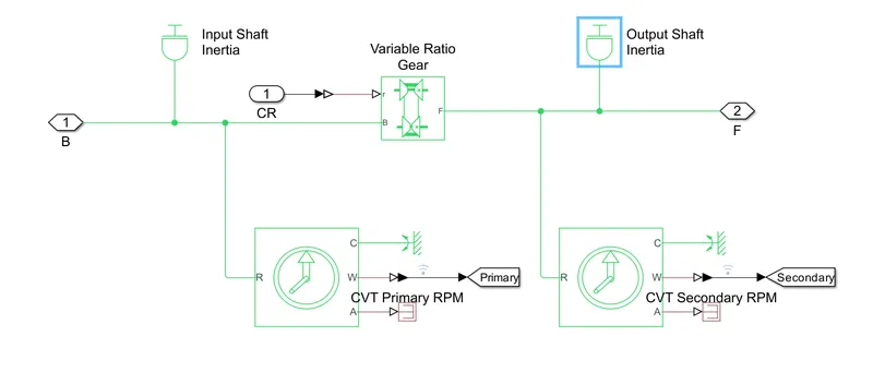
In this model of CVT, two spinning inertias are connected to the input shaft and output shaft of the variable transmission gearbox. The inertias spin with the different angular velocities along with the two shafts that are coupled by a gear. These inertias will experience different torques. They are actuated by an external torque produced by the engine through the engine sensor block. Engine sensor block is connected such that the initial velocities of both the shafts are set to zero and the default follower-base gear ratio value to 10. The CVT block accepts the continuously varying gear ratio as a physical Simulink signal through the extra physical signal input labeled 'r. So we need to create a variable signal for the gear ratio with a Signal Builder from the Simulink block library and Simulink PS Converter block. Build a signal that rises with a constant slope from 1 to 4 over 10 seconds. Then connect the converted physical signal to the r port.
We need not change the other, original settings of the simple gear model. The angular velocities and torques of the two shafts have the same signs. The ratio of angular velocities and torques will be at 10, as the gear ratio is set at 10. As the gear ratios decrease towards 1, the angular velocity of inertia 2 becomes greater than the velocity of inertia 1 while the associated torque in the second shaft becomes smaller than the torque in the first shaft. Because the gear ratios changing, the motion and torque do not follow the sine wave.
Due to other vehicle parameters, the inertia rotational torque values may vary from the provided engine torque value. The CVT plays an important role in manipulating these torque values of shafts to bring to the fixed gear ratio provided by the simple gear. By doing this the fuel consumption by the engine will be reduced and the performance of the engine will be improved.
To create this model, from Simcape driveline, simscape, and Simulink block libraries, drog and drop two inertia, two ideal rotational motion sensor, two mechanical rotational references, and two PS-Simulink Converter and from simscope utility library, drag a solver configuration block which is mandatory for every distinct driveline block diagram CR tog provides the CVT ratio from the Signal Builder block to the subsystem CVT. The ideal motion sensors will measure the angular velocities of two shafts and are tagged to Goto blocks Primary and Secondary tags such that data can be displayed by a scope block using Form tags, Primary and Secondary. Form togs receive data from Goto tag by connecting with visualize signal(wifi signal)
CVT Subsystem Model:
Vehicle Body subsystem:
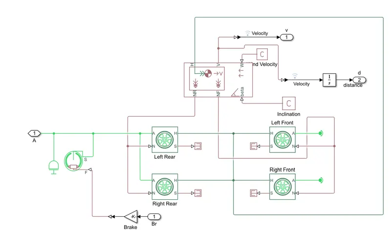
- The Vehicle Body accounts for body mass, aerodynamic drag, road incline, and weight distribution between axles due to acceleration and road profile.
- The Double-Shoe Brake is to apply brakes to the rear wheels. With this component, two brake blocks are applied at opposite ends of the drum. This prevents an unbalanced force from acting on the shaft and bearing connecting the drum to the wheel, which would be the the case with a single-shoe brake.
- All of the above is applied to the four wheels
BAJA ATV Model with Dashboard:(SINGLE LOOP)
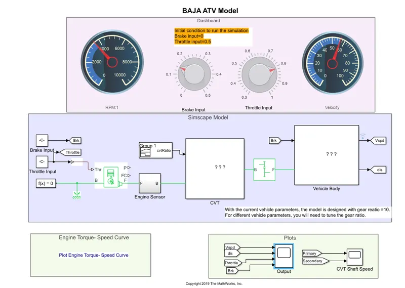
INPUt & OUTPUT
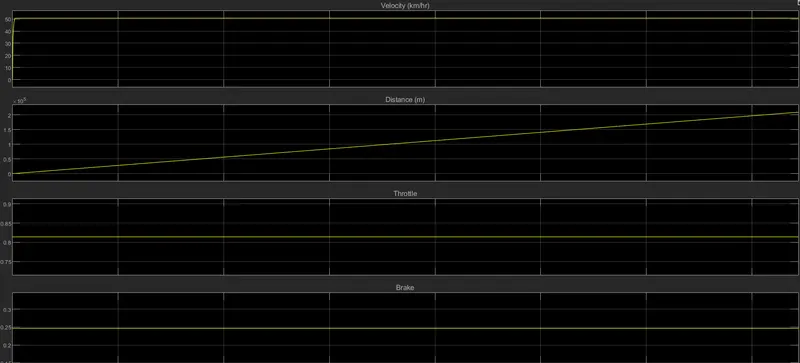
BAJA CVTModel_with mapped: (Closed Loop)
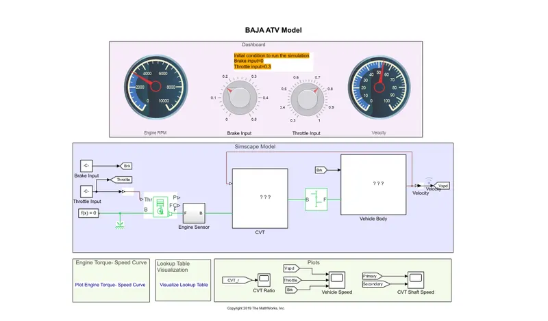
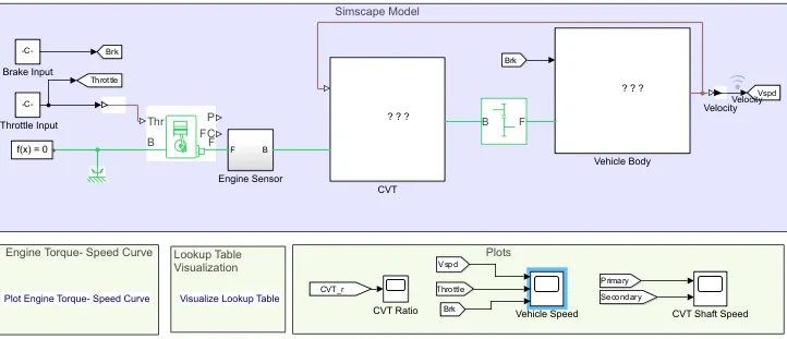
In this model brake input and throttle input are given through constant blocks instead of signal Builder by just turning the knobs. We can input any value and observe the vehicle behavior within less span of time. The output velocity is taken as input to the PS Lookup table which is connected in CVT Subsystem. Lookup table data also imported from the workspace which provides variable gear ratios to the CVT subsystem. The results are observed after doing the simulation. The dashboard is provided to this model to give variable input values for brake and throttle input. These blocks are given connection to the model by selecting the radio button under connection in the popup window of circular gauges.
BAJA CVTModel_dash board: (Closed Loop)