Project
AIM- To design a BAJA All Terrain Vechile (ATV) Model Using MAtlab and Simulink .
Structure: Basic Requirements to design a vechile are,Engine ,Vechile Body,Sensors,Gearbox,Throttleinputs,Brakes, ETC.
In this Design we used The CVT (contininous Variable Trasnmission) for the Generating the higher Gear Ratio and higher Torqure to RPM Efficiency.
ATV is design on basies of combination of simulink and simscape blocks in the matlab.
CVT is the main component of the ATV so,firstly will design CVT
NOw, WHAT is CVT ?
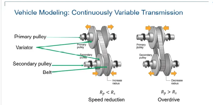
In this image you can the Visualize the CVT
When the variator of the primary pulley increases or expand in the outward direction there is a increase in the radius of the secondary variator this phenomena result to speed reduction of the CVT where as,
the primary variator compacts inside as shown in figure, then radius of the secondary variator decreases and we get and Over drive
here the Transmission is done through belt drive .(image refer from Mathworks.com)
Now when we Modify this into sumilnk by using simscape block its Looks Like (Refer Image).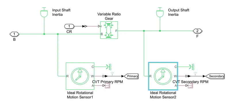
We have used a Variable gear ratio block ,inertia Block for input and output , 2 ideal rotational sensor for input and output and ps terminator for motion sensor as we does not need the angle of the ratating shaft, its avoid the error.
Now We will design the vechile Body.
generally the vechile consist of ,Vechile Body ie: the Upper part and tyres of the Vechile on which the Body is Maounted .
it is very simple to design the vechile body in simulink bcz,simulink has the total ready made block of the vechile in the foundation library .
(refer image).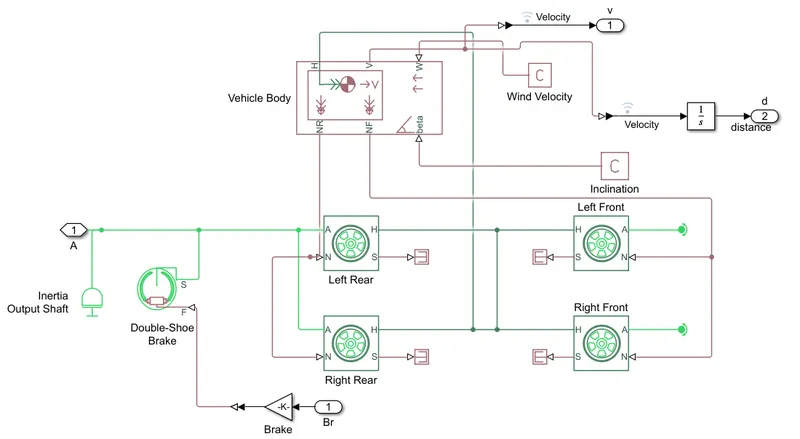
As you can see the design consist of Vechile body block ,4 tyres, Brake, etc.
here we can see in vehicle body ,NR NF are normal force of front wheel and normal force of rear wheel
H is for force transmission or HUB that transfer the force fromt the wheel.
beta indicates the inclination angle if the vehicle is driving at some angle ie upwards or down wards it can be + or -
- for downwards and + for upwards w
W indicates the wind
V indicate the Velocity of the vehicle .
Now considering the tire, H is for HUB
N is the normal force
A is the For Axel .
S indicates the slip of the tire.
This is the normal condition of the vehicle ,but practically Values are gradually changes with respect to time,speed and torqure.
So, A 1 D look up table is used in between the vehicle body and tire of the design that give the Consideration value of the system or design.
Look up tables give you to interapolation and extrapolation values.
Here , throttle and brakes inputs are give to engine through a signal builder block .
output of the enhine is given to the input of the CVT .to measure the rpm of the engine a sensor is used to the output shaft (block name is given as enhine sensor) it is nothing but the Ideal Rotaional motion sensor .
As the our model is very vast ,so FROM and GOTO ports are used to see the result ,using this port our design looks compact and sestematic.
For better visualizing we have connected our Engine RPM to the coustamise gauge found in simulink library-dashboard with setting given to 10000 RPM ,another gauge we have added to Velocity of the vehicle .
slider knob are aslo added to the brake and throttle inputs. (open and run the CVT dashboard File).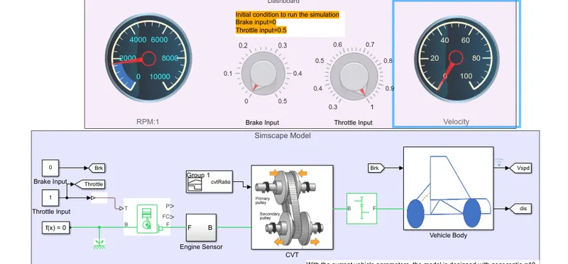
Results: By changing the layout the scope All the result are seen in the single Scope By Incresing th axis to 4 ie Velocity ,Distance , throttle and brakes.,direct connection are not seen bcz we have used FROM and GOTO ports.
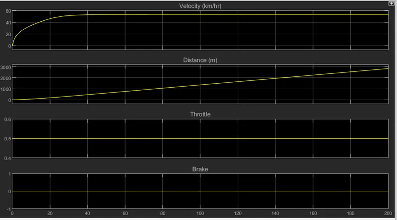
Results are capture From Running the simulation for 200 sec .