Project 3: Roof Modeling
Objective:
To design a car roof and test if it satisfies heat distortion criteria, snow load criteria, Stamping requirements (Draft analysis), master section analysis.
Introduction:
An automotive roof is a part which sits above the passengers’ compartment protecting the passengers from sun, rain, dust, snow etc. There are different types of roofs depending on the type of car. Some of them are sunroofs, hardtops, convertibles, vinyl roofs etc. In this roof design we are looking into the most common type of roof that is hardtop.
A car roof serves many purposes. A few are:
- Protects passengers from wind, rain, snow etc.
- Provides safety to the passengers from accidents in which roof is involved.
- Provides aerodynamic shape to the car.
- Improves aesthetic look of the car.
Main points to cover in this report:
- Design of ditch area and reinforcements.
- Calculations to test whether the bow roofs, center roof rail, front roof and rear roof are positioned correctly.
- Section modulus of both the bow roof rails and the center roof rails.
- Draft analysis.
Design of ditch area:
A roof ditch area extending generally in a longitudinal direction is fixedly coupled to a body member and forms a longitudinal water management channel on the lateral side portion of the roof of the car.
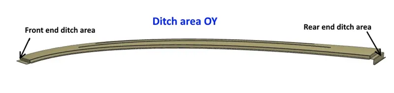
Reinforcements:
- Front roof rail.
- Bow roof rail 1.
- Center roof rail.
- Bow roof rail 2 .
Front roof rail:
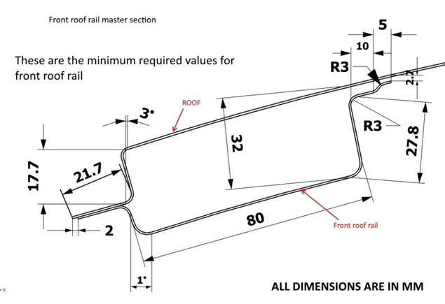
The above figure shows the master sketch of the front roof rail with minimum required dimensions. This railing provides strength to the front part of the roof. The front roof rail is joined with windshield glass, body side outer panel and inner panel. We provide a 3-5 degree draft angle depending on the visibility criteria. The windshield glass is spot welded on one end and the other side of the end is joined with the roof using mastic sealant.
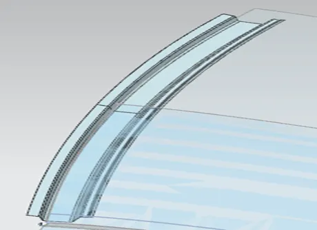
Bow roofs 1 and 2:
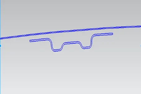
Bow roofs also strengthen the roof. These railings should satisfy the head room clearance condition and also 3-5 degree draft is to be applied as this part is deep drawn. These railings are attached to the roof inner panel using mastic sealants. For applying these sealants we have to give a gap of 5mm. The bow roofs are thickened in the upward or inside direction. The outer panel is also thickened in the inward direction. 0.75mm is the applied thickness. A positive draft angle is maintained so that the punch is removed easily without damaging the sheet. Blends are also applied so that there are no sharp edges.
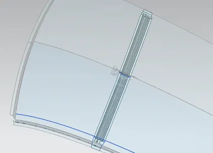
Center roof rail:
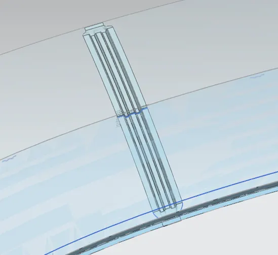
Center roof rail is wider than bow roof rail. The purpose of center roof rail is also to increase the strength. This rail is also attached to the inner panel of the roof with the help of mastics. Hence a gap of 5mm plus thickness is given.
Rear Roof Rail:
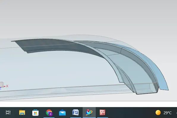
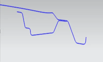
Rear roof rail joins the back door and the body side outer. Rear head room clearance and rear visibility criteria are taken into account. Rear roof rail has a different design because back door is mounted using hinge mechanism.
Heat distortion study on roof:
Heat distortion temperature is the temperature limit above which the material cannot be used for structural applications. This study helps us to predict the heat distortion temperature at which the material starts to soften when exposed to a fixed load at elevated temperatures. This study helps us to predict the bow roof position which strengthens the roof.
Bow–roof prediction Formula
W = [1.73 x 10^ (-3) x L] + [1.85 x 10^ (-8) x (R^2)/t] + [1.10x10^ (-3) x l] - 2.68
Judgement Condition: OK< 2.7> 3.1
Where
L = Roof Length in X-Direction [mm] (Roof dimension in 0-Y)
R = Roof curvature
R = 2(Rx*Ry)/(Rx+Ry)
Rx = X curvature
Ry = Y curvature
t = Roof plate thickness [mm]
l = Bow Roof Span [mm]
Snow load Prediction formula
Qr = [Iy x t2] / [α x s x [(Rx + Ry)/2]2 x 10-8]
Note: The Qr value given over here is correct. There was a typo error in the formula given in the video.
Where
α = My x Lx2 x 10-12 , My = Y(Ly-Y)
Judgement condition = Qr ≥ 3.1
250 ≤ s ≤ 380
t = Roof plate thickness [mm]
Ly = Distance between the front and rear roof Rails on the Vehicle along with 0Y[mm]
Length of Roof panel with the center point between Roof rails Front /Rear as the front and rear reference point.
Lx = Distance between the Left and Right end of the roof on the Roof BOW [mm]
Width of the roof panel exposed on the surface.
Y = Distance front Front Roof Rail to Roof BOW [mm]
s = Distance for which Roof BOW bears divided load [mm]
s = L1/2 + L2/2
Iy = Geometrical moment of inertia of Roof BOW (Y cross-section )[mm4]
Rx = Lateral direction curvature radius of roof panel Y cross-section on Roof BOW [mm]
Roof panel curvature Radius of the Length Lx in Front view
Ry = Longitudinal Direction curvature radius of the Roof panel X cross-section on Roof BOW [mm]
Draft analysis:
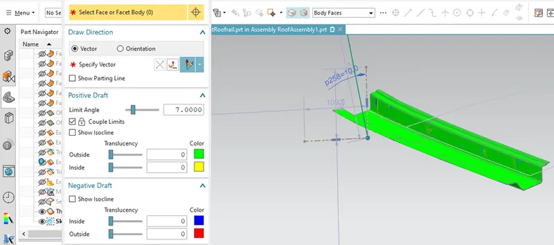
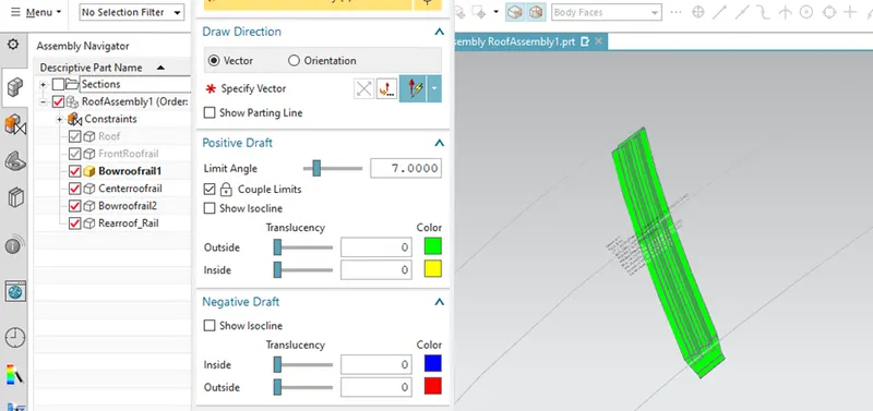
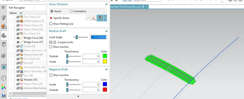
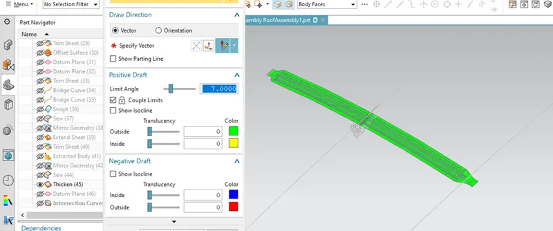
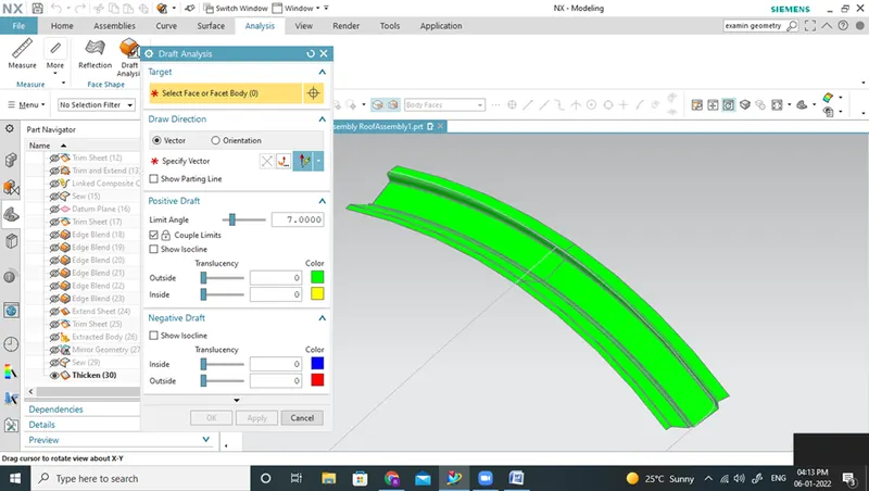
Draft analysis is a method of checking the draft angle on various faces of a part with a particular direction. It makes sure that the stamping or deep drawing process is done with a positive draft angle of about 7 degrees, so that the sheet doesn’t get damaged while removing the stamp.
Front Roof Rail: For the front roof rail I had to give an inclined tooling direction. The angle being +10 degrees with respect to the Y-axis. Once this tooling direction is fixed I am able to get a clear front roof rail.
Bow Roof rail 1: For bow roof rail one the usual Y-axis is taking as the tooling direction and it has cleared without any issues.
Center roof rail: For center roof rail the draft analysis is cleared with a tooling direction of the usual Y-axis.
Bow roof rail 2: Bow roof rail 2 has also cleared with a tooling direction of the usual Y-axis.
Rear Roof Rail: Rear roof rail has also successfully cleared with a tooling direction of Y-axis.
Conclusion:
The roof along with its reinforcements has undergone draft analysis, snow load criteria, heat distortion condition. Section modulus was also found out. The results have been documented.