Project 3
Design and simulation of Buck converter for Auxiliary load in EV.
- Input voltage is 48V, the Output voltage is 12 V
- Load current is 10A
- Calculate Duty ratio and Load(use Resistor as Load)
- Calculate L, C
Buck Converter is the DC-DC nonisolated converter. It steps downs the input voltage to the desired output voltage.
The model consists of a DC voltage input of 48v, Mosfet semiconductor switch whose switching action is controlled by the PWM signals created by the pulse generator in this model. The model has a diode, inductor, capacitor, and load resistor as shown below.
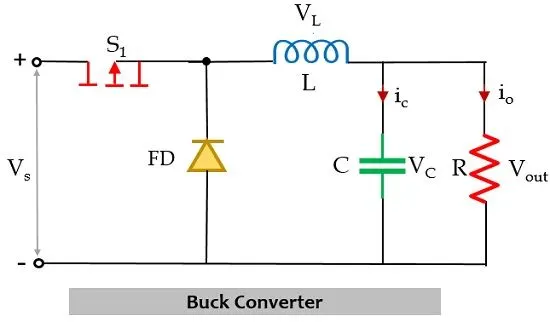
When the switch is closed the current from the input starts flowing through the MOSFET for a period of DT (duty cycle and time period) and charges the inductor since the potential of the diode is reverse-biased. The inductor does not allow sudden changes in current and it acts as a current source for a limited period when the switch is open.
When the switch is open for a period (1-D)T, there is no current from the input source thus the energy stored in the inductor is released ad the current flows through the diode. Increasing the inductance value can reduce the ripple of the output current.
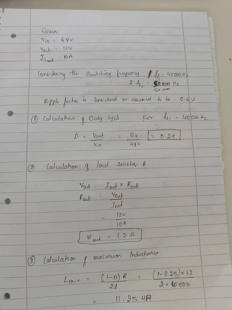
Here in the design, I have considered two switching frequencies fs1=40000 and fs2=50000 for analyzing the output current.
Since the output voltage required is 12v the appropriate inductance value, capacitance value, and load resistor value have to be determined as also the duty cycle for how long the switch should be closed is to be determined.
Calculations:
Duty cycle= Vout/Vin
Load resistor= Vout/Iout
Minimum Inductance Lmin = [(1-D)*R] / (2*f)
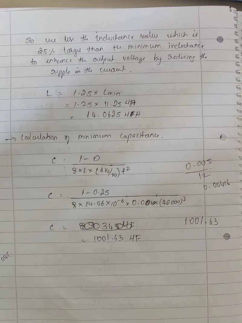
Maximum Inductance L = 1.25 * Lmin
Capacitance C = (1-D) / (8*L*r*f^2)
Ripple factor r = Change in output voltage / rated output voltage
The values calculated for the different switching frequencies are shown in the Picture attached.
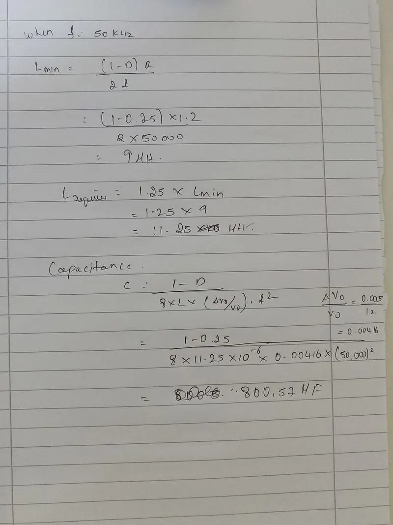
From the analysis of both the switching frequency, it can be clearly observed that the output voltage from the model is 11.34V and the load current is 9.45A.
This might be because of the switching losses, and conduction losses the efficiency of the converter is reduced.
The converter is designed to be 94.5% efficient.
Another observation is the current ripple is reduced with an increase in the switching frequency. Thus the average output voltage is current is close to the desired values.