Project 1
Aim - This Project Motive is the we controlled our Fan speed with Help of the PWM For this Modulate Simulink Model we can see in deatil
Working-
By controlling the electrical parameter of motor result in change of speed of Fan. Fan connected on shaft of DC motor.
A DC motor consist basically of two parts, the stationary body of the motor called the “Stator” and the inner part which rotates producing the movement called the “Rotor”. For D.C. machines the rotor is commonly termed the “Armature”.
So Now we see the How Design Load in this Project
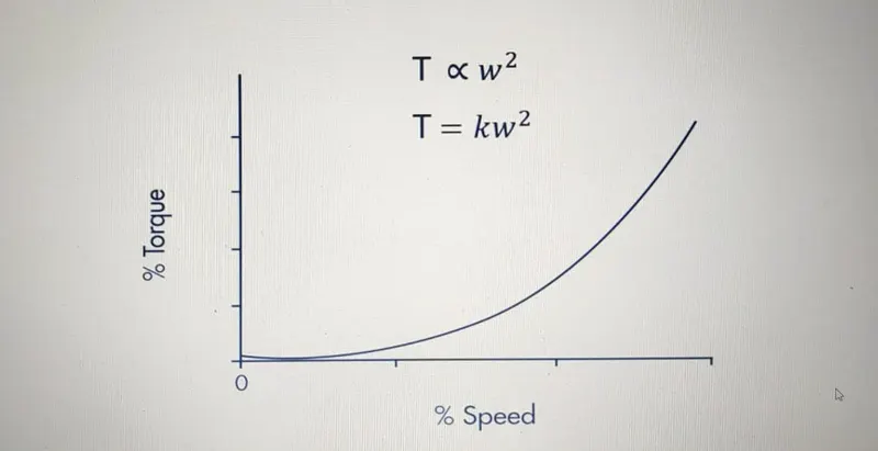
Torque exerted by fan represented by TL
Load torque i.e. TL proportional to square of speed i.e. wm^2
TL = C . wm^2
By varying the electrical parameter of motor i.e. voltage and current we are controlling load torque or load speed.
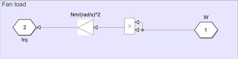
For fan load we don’t have any block to represent a fan so we are representing by a subsystem
our speed torque characterstics fan load
Now we see The Total Model Of this Project
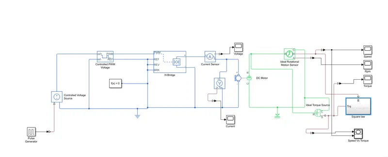
In this Circuit We used the Pulse Genrator Block For the Generate the pulses .Then We used the Controlled Voltage Block For The Giving The Supply to the Controlled PWM Voltage it will create the Pulses And Given to the H - Bridge controlled the motor with help Pulses H-Bridge Given Supply to the Motor and Motor Mechanical Part Connected to Ideal Rotion Motion Sensor so it will sense the Motion
And our Load we Connect to the Ideal Rotion sensor W port to the Square law Port and Another Port of the Square law Block is Toruqe we connected to the Idel torque sources this block connected to the Motor C And R port so it will create torque on motor shaft
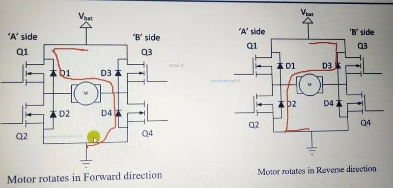
IF we Observed the our H-Bridge work like this For the when the our supply is on that time Q1 and Q4 switch is on so our circuit will be compete when our supply is Off that time Q2 and Q3 switch on motor start working on reverse Direction
We take Pulse period is 50 sec And Ton=Dutcy cycle= 50%
Ducty Cycle Formula Is Ton/Ton+Toff*100%
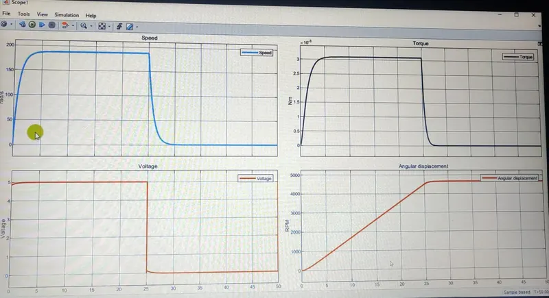
Our Volatge ,Speed ,Torque ,RPM graph look like this we take Period is 50 sec so it will run for 50 sec and ducty cycle is 50% so our output we can trun on for only for the 25 sec then turn off . we can see our speed rapdily increses goes to the top speed but 25 sec it will come down toruqe also same
But this example Not work inreal Because of our fan Speed not inceres rapdily it will increse gradully
So now we see the real word fan example with help help reapting squance satir Block
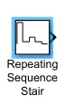
we get result like increses our fan speed like controlled througe requaltor this now look like real fan example and we can controlled tha fan properly
we can see now our spped graph increses step wise during on time when it will off it goes down also step wise same for torque ,Voltage and we angular displacemnt graph aslo increses gradully
Period 30 sec ducty cycle 50%
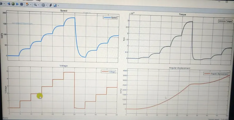
Conclusion - We can see in resulte we can controlled our fan with help PWM with help Of DC Motor we can see Practical Example of Fan how work in daytoday life . so we can controlled our fan done